24

RC — Serviceability: Deflections & Crack Control

01

Engineering story

A century of steel — from concept to skyline

Engineer reviewing blueprints against a steel-frame construction site at sunrise

Strength keeps the beam standing; serviceability keeps the owner happy.

Effective moment of inertia Ie (Branson) turns a cracked beam into a workable stiffness.

Chapter 24 covers immediate + long-term deflections, Branson's Ie, ACI 318-19 Table 24.2.2 limits (L/240, L/360, L/480), and modern crack-control detailing.

Iconic steel structures built on engineering excellence
  1. Branson's Ie
    1965
  2. ACI 318 Ie in code
    1971
  3. ACI 318-19 (current)
    2019
Load pathService D+L (unfactored)Cracked section IcrIe via BransonΔimm + ΔlongCompare to L/limit
02

Learning objectives

What you will be able to do after finishing Chapter 1 — and why each objective matters in practice

Compute Ie (Branson)Objective 01

Compute Ie (Branson)

Ie = (Mcr/Ma)³·Ig + [1−(Mcr/Ma)³]·Icr ≤ Ig.
Why it matters
Blends elastic and cracked stiffness.
Where it is used
Every RC deflection.
Connects to
ACI 24.2.3.5.
Immediate deflection ΔimmObjective 02

Immediate deflection Δimm

Δimm = 5·w·L⁴/(384·Ec·Ie) for a simply supported UDL beam.
Why it matters
The visible sag at service load.
Where it is used
Everywhere deflection matters.
Connects to
Mechanics + ACI 24.2.
Long-term multiplier λΔObjective 03

Long-term multiplier λΔ

λΔ = ξ/(1 + 50·ρ'); ξ = 2.0 for 5+ years. Δlong = λΔ·Δsustained.

Why it matters
Creep and shrinkage add 100-200% to Δimm.
Where it is used
Every long-term check.
Connects to
ACI 24.2.4.1.
Apply ACI Table 24.2.2 limitsObjective 04

Apply ACI Table 24.2.2 limits

L/240 flat roofs, L/360 floors, L/480 supporting sensitive finishes, L/240 total long-term.
Why it matters
Owner expectation, cladding tolerance.
Where it is used
Every serviceability check.
Connects to
ACI Table 24.2.2.
Crack-control spacing sObjective 05

Crack-control spacing s

s = 15·(40,000/fs) − 2.5·cc; ≤ 12·(40,000/fs). fs ≈ 0.67·fy.

Why it matters
Keeps flexural cracks < 0.016 in wide.
Where it is used
Rebar spacing detailing.
Connects to
ACI 24.3.
Deflection alternatives (min h)Objective 06

Deflection alternatives (min h)

For non-prestressed beams supporting non-sensitive elements, min h = L/16 simply supported, L/18.5 one end continuous, etc.

Why it matters
Bypasses deflection calc when limits met.
Where it is used
Fast preliminary sizing.
Connects to
ACI Table 9.3.1.1.
03

Engineering motivation

What each part of a steel-frame building actually does — and why it exists

Before you design any single member, you have to see the whole system. A steel-frame building is not a collection of independent shapes bolted together — it is a deliberate load path, engineered so that every kilonewton of gravity, wind, or seismic demand has a continuous route from where it starts to the ground where the earth can resist it.

The photograph below shows a typical steel framing detail. Drag each labelled chip onto the structural element it names — the drop is only accepted when it lands inside the correct element's outlined region. A correct answer locks in with a green outline and a short explanation; a wrong answer flashes the region red, tells you what you actually hit, and returns the chip so you can try again. Press Reveal expected placements to see the reference solution (that attempt is then marked as assisted).

Structural steel framing — identify each element by dragging the labels
Fig. 1.3 · Drop a chip inside the outlined element it names. Green = correct and locked; red flash = wrong element, chip returns.
04

Failure mechanisms

Why we design the way we do — six ways steel structures have failed, and what each disaster taught the profession

Every provision in AISC 360 is a scar. Behind each equation, load factor, and detailing rule is a bridge, a walkway, or a tower whose failure cost lives and rewrote the profession. The six case studies below trace the mechanisms that motivate the code you are about to learn.

Read each one as an engineer, not a spectator: identify the load, the limit state, the missing check, and the specific clause that exists today because that check was missed. When you meet those clauses again in Chapters 5–17, they will read as answers, not rules.

Excessive long-term deflection: Cantilever balcony sags visibly over years.
Case 01
Fig. 1.4.1 · Excessive long-term deflection
Failure mechanism

Excessive long-term deflection

Cantilever balcony sags visibly over years.

Root cause

λΔ underestimated; A's = 0 so ρ' = 0.

Lesson learned
Add compression rebar to reduce λΔ.
§ACI 24.2.4.1
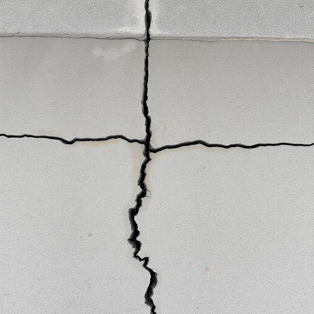
Wide flexural cracks: Cracks > 0.016 in expose rebar to corrosion.
Case 02
Fig. 1.4.2 · Wide flexural cracks
Failure mechanism

Wide flexural cracks

Cracks > 0.016 in expose rebar to corrosion.

Root cause

Rebar spacing s too wide; fs too high.

Lesson learned
Reduce s or use smaller bar sizes.
§ACI 24.3
How failure propagates
The five-stage failure progression
1Service load
2Compute Ma
3Ie via Branson
4Δimm
5Δlong via λΔ
6Compare to limit

Design codes intervene at the transition from yield to instability. Everything before yield is elastic and reversible; everything after instability is a race to collapse. LRFD keeps the demand well below the first transition.

05

Lecture notes

The full textbook chapter — figures, equations, and engineering narrative

Reflection · Think before you read

A beam satisfies every strength requirement but sags noticeably over a few years. What creep and shrinkage mechanisms cause that long-term deflection, and how does the effective moment of inertia Ie try to capture the cracked reality?

How this chapter is organized. A structure passes every strength check (Chapters 22, 23) and can still be a bad building — floors that sag, doors that jam, plaster that cracks. Serviceability is the second family of limit states, checked at service (unfactored) loads. We start with the ACI code framework, then compute immediate deflection with the effective moment of inertia Ie, add long-term creep and shrinkage with λΔ, and close with McCormac Example 6.1 and the crack-control spacing rule.

1 · Limit-States Philosophy (McCormac §6.1)

FamilyGovernsLoad levelFailure consequence
StrengthBuckling, fracture, fatigue, overturning, collapse (Chapters 22, 23)Factored (γD·D + γL·L + …)Life-safety — collapse or loss of load path
ServiceabilityDeflection, crack width, vibration, surface deteriorationService (unfactored)Usability — damaged partitions, ponding, jammed doors, corroding rebar

The most common serviceability failure in RC buildings is partition damage from long-term creep-driven deflection — the slab keeps sagging for years after construction while the rigid masonry wall on top does not. Gypsum-board partitions are more forgiving; masonry is not.

2 · Two Ways ACI 318-19 Controls Deflection (§6.3)

(a) Minimum thickness rules. ACI Table 9.22.2.1 (beams) and 7.22.2.1 (slabs) give an h/L ratio that historically produces acceptable deflections. Meet it and you are allowed to skip deflection calculations — unless the member supports partitions or non-structural elements likely to be damaged.
(1)
(2)
(3)
(4)
(b) Compute Δ and check against limits. If you cannot (or choose not to) meet the minimum thickness — or if the member supports sensitive elements — you must compute Δ and compare it with ACI Table 24.2.2.
(5)
(6)
(7)
(8)

3 · Elastic Deflection Formulas (McCormac Fig. 6.2)

Immediate deflection uses the same textbook elastic formulas you learned in Statics — but with Ec·Ie as the flexural stiffness. Loads are service (unfactored). Continuous beams are often approximated as simple beams with a correction for end restraint.

(a) Simple beam, w Δc = 5·w·L⁴ / (384·E·I) (b) Fixed–fixed, w Δc = w·L⁴ / (384·E·I) (c) Cantilever, w Δtip = w·L⁴ / (8·E·I) P (d) Simple beam, P at midspan Δc = P·L³ / (48·E·I) P (e) Fixed–fixed, P at midspan Δc = P·L³ / (192·E·I) M (g) End moment on simple beam Δc = M·L² / (16·E·I)
Figure 6.2 — key elastic deflection expressions (McCormac). E = Ec, I = Ie.

4 · Effective Moment of Inertia Ie (§6.5, Branson)

When Ma < Mcr, the section is uncracked and behaves like a homogeneous elastic beam with I = Ig. As soon as Ma exceeds Mcr, tension cracks propagate and rigidity drops toward Icr (transformed cracked section). Real beams live between the two — parts of the length are cracked, parts are not. Branson smoothed this transition into a single formula, adopted verbatim by ACI 318 as Equation 24.2.3.5a (historically 9-8):

Branson's effective moment of inertia (ACI 24.2.3.5a)
(9)
Cracking moment (see Ch. 22 §3)
(10)
Modulus of elasticity (ACI 19.2.22.1)
(11)

Every load level has its own Ie. Dead load → Ie(D). Dead + live → Ie(D+L). Dead + sustained live → Ie(D+SL). This is why the live-load deflection is never just the LL formula — it is the difference of two full deflections with different Ie.

I Ma Ig Icr Mcr Ie = Ig for Ma < Mcr Branson transition approaches Icr for large Ma
Figure 6.3 — Ie transitions from Ig (uncracked) toward Icr as service moment Ma grows past Mcr.

5 · Long-Term Deflections — Creep & Shrinkage (§6.6)

Concrete creeps under sustained stress and shrinks as it loses moisture. Both mechanisms slowly increase the deflection produced by any load that stays on the beam. ACI captures both into one empirical multiplier applied to the sustained-load immediate deflection:

Long-term multiplier (ACI 24.2.4.1.1)
(12)
Duration of sustained loadingTime factor ξ
≥ 5 years2.0
12 months1.4
6 months1.2
3 months1.0

Why compression steel matters. The (1 + 50·ρ') denominator makes A's the cheapest way to control creep deflection: doubling ρ' from 0 to 0.01 cuts λΔ in half. Every doubly-reinforced beam gets long-term deflection control almost for free.

6 · Total Long-Term Deflection — the Full Recipe (§6.6)

Long-term deflection
(13)
Step-by-step.
  1. Compute ΔD from D alone with Ie(D).
  2. Compute ΔD+L from full D+L with Ie(D+L).
  3. ΔL = ΔD+L − ΔD (immediate live-load deflection).
  4. Compute ΔD+SL from D + sustained fraction of L with its own Ie.
  5. ΔSL = ΔD+SL − ΔD (immediate sustained-live deflection).
  6. ΔLT = ΔL + λ·ΔD + λt·ΔSL. Compare with ACI Table 24.2.2.

7 · Worked Example — McCormac Example 6.1

Given. Simple span L = 20 ft. b = 12 in., h = 20 in., d = 17 in., 3 #9 tension bars (As = 3.00 in²), A's = 0. f'c = 3,000 psi (NWC), fy = 60 ksi. Service DL = 1.0 klf (includes self-weight), service LL = 0.7 klf. 30% of LL is sustained for 3 years.
(a) Immediate dead-load deflection ΔD
(14)
(15)
(16)
(17)
(18)
(19)
(20)
(b) Immediate D + L deflection ΔD+L
(21)
(22)
(c) Immediate live-load deflection ΔL
(23)

ACI Table 24.2.2 row 2 (floor, LL immediate): L/360 = 240/360 = 0.667 in. → 0.222 < 0.667 ✓

(d) D + 30% sustained LL — ΔSL
(24)
(25)
(26)
(e) Long-term multipliers
(27)
(28)
(29)
(f) Total long-term deflection ΔLT
(30)
(31)
Compare with ACI Table 24.2.2:
• Supporting elements likely to be damaged: limit = L/480 = 0.500 in. → 0.838 > 0.500
• Supporting elements not likely to be damaged: limit = L/240 = 1.000 in. → 0.838 < 1.000

Fixes if L/480 governs. (1) Add compression steel A's — even 2 #6 (ρ' ≈ 0.0043) cuts λΔ to about 2.0/(1+0.215) ≈ 1.65, dropping ΔLT below 0.72 in. (2) Deepen the beam — Ie grows with h³. (3) Camber the beam upward by the sustained deflection (McCormac Fig. 6.1).

8 · Continuous Beams (§6.8)

A continuous beam has different Ie along the length — the flange is often uncracked at midspan and cracked at supports (or vice versa for a T-beam). ACI §24.2.3.6 permits a weighted average:

Weighted average (ACI §24.2.3.6, one variant)
(32)

where Ie,m is midspan and Ie,1, Ie,2 are the two end sections. For approximate hand calculations, use Ie,avg = ½·Ie,+ + ¼·(Ie,−left + Ie,−right) — McCormac §6.8.

9 · Crack-Control Reinforcement Spacing (§6.9, ACI 24.3)

Cracks are unavoidable in RC; the design goal is to make them narrow and closely spaced rather than wide and infrequent. ACI 24.3.22.1 limits the bar spacing (measured c/c of the closest bars) as follows, using the service-load steel stress fs (usually taken as ⅔·fy = 40,000 psi for Gr 60) and the clear cover cc:

Crack-control spacing — both must be satisfied
(33)

Rule of thumb. For Grade 60 rebar with ¾-in. clear cover, s ≤ 15 − 1.9 = 13.1 in. and s ≤ 12 in. — so 12 in. governs. Small-diameter bars, close together, always beat a few large bars far apart.

⚠ Common Mistakes in RC Serviceability

  • Using factored loads for deflections. Deflection is a service check — use unfactored D, L.
  • Using Ig even when Ma > Mcr. That underestimates deflection by a factor of 2 or 3.
  • Recycling one Ie for every load level. Each of D, D+L, D+SL has its own Ie — compute all three.
  • Multiplying the immediate D+L deflection by λΔ. λΔ applies only to the sustained portion — dead load plus the sustained fraction of live load.
  • Comparing ΔLT to L/360. That limit is for immediate live-load only. Long-term uses L/480 (sensitive elements) or L/240 (not sensitive).
  • Ignoring A's in λΔ. Compression steel is often the cheapest fix.
  • Forgetting the minimum-thickness rule (ACI 9.22.2.1) — if h ≥ L/16 (simply supported, Gr 60) and no sensitive partitions are supported, you can skip the deflection calculation entirely.

10 · Using ACI 318-19 Tables & Design Aids

TableGives youHow to read
ACI Table 9.22.2.1Minimum beam depth h vs L (Gr 60)Read span type (SS, one-end continuous, both, cantilever) → get h/L.
ACI Table 7.22.2.1Minimum one-way slab thicknessSame idea, for slabs; adjust for fy ≠ 60 ksi.
ACI Table 24.2.2Maximum permissible computed ΔMatch your case (roof/floor, immediate/long-term, sensitive/not) → read L/x limit.
ACI Table 24.2.4.1.3Time factor ξEnter with load duration → read ξ (2.0, 1.4, 1.2, 1.0).
ACI Table 24.3.22.1Bar spacing for crack controlEnter with fs and cc → read smax.
06

Professional practice, safety & ethics

RC serviceability practice

Professional practice
  • Long-term deflection with sustained load multiplier λΔ is typically 2–3× the immediate value — communicate expected values to the architect.
  • Camber, cambered formwork, and construction sequence all affect final elevations.
  • Crack control is a durability requirement: bar spacing per ACI §24.3 controls corrosion exposure.
Safety in design & construction
  • Excessive deflection can fail glazing, partitions, and drainage — a serviceability failure can become a safety failure by ponding.
  • Early formwork removal is a leading cause of excessive long-term deflection and construction collapse.
  • Restrained shrinkage cracking near supports is normal; wide flexural cracks are not.
Engineering ethics
  • Do not ignore reported cracking; investigate and document the cause.
  • Disclose realistic deflection expectations before the finishes are selected.
  • Do not use Ig where Ie is required to make a deflection check pass.
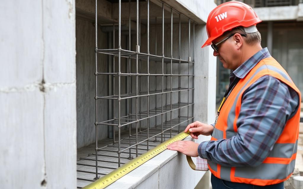
Inspector verifying reinforcing bar size, spacing, and cover before a concrete pour
Field inspection: rebar size, spacing, and cover verified before placement.
Engineers reviewing sealed structural drawings across a conference table
Design review: documenting assumptions before the drawings are sealed.

ABET / licensure link. These points map to ABET Student Outcomes 2 and 4 — engineering design within realistic constraints, and recognition of ethical and professional responsibilities. Expect NCEES FE and PE exam questions on the NSPE Code of Ethics, OSHA construction requirements, and the engineer's standard of care.

07

Cost analysis

Serviceability cost

Approach
  • Meeting deflection limits usually means depth, and depth in concrete is cheap compared to added steel.
  • Cracking repairs and finish damage after occupancy cost far more than the design-stage depth increase.
  • Long-term deflection (λΔ) is where complaints originate; design for the 5-year value, not the immediate one.
Worked cost example — Adding 2″ of depth vs post-occupancy repair
Basis: 24-ft span RC beam
Line itemQtyRateCost
Extra concrete + formwork for +2″ depth
1 ls$340$340
Partition/finish repair after excess deflection
1 ls$6,500$6,500
Extra rebar to control cracking
0.02 ton$2,200$44
Estimated total$6,884

Takeaway. ≈$384 now versus $6,500 later — serviceability is the cheapest insurance in concrete design.

Unit rates are representative US averages for teaching purposes. On a real project, price with current local rates (RSMeans, fabricator quotes, or contractor pricing) and state the estimate date.

08

Animated concepts

Key mechanics visualised — watch the strain profile, stress block, or buckled shape evolve

Long-term deflection (creep + shrinkage)
t = 0 (elastic)t = ∞ (creep + shrinkage)Δ_LT = (1 + λΔ)·Δi · λΔ = ξ/(1 + 50ρ′)Δ = 12.0 (rel.)

Instantaneous elastic deflection Δi grows to Δ_LT = (1 + λΔ)·Δi over time — ACI 24.2.4 multiplier.

09

Engineering figures

Full-page reference diagrams — the visual vocabulary you will use for the rest of the course

§24.6.1

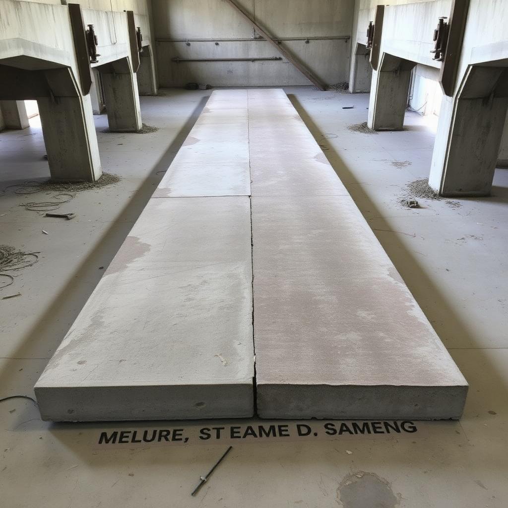
Long-span sag

Deflected slab
Fig. 24.1Deflected slab

Service Δ is what the occupant feels.

§24.6.2

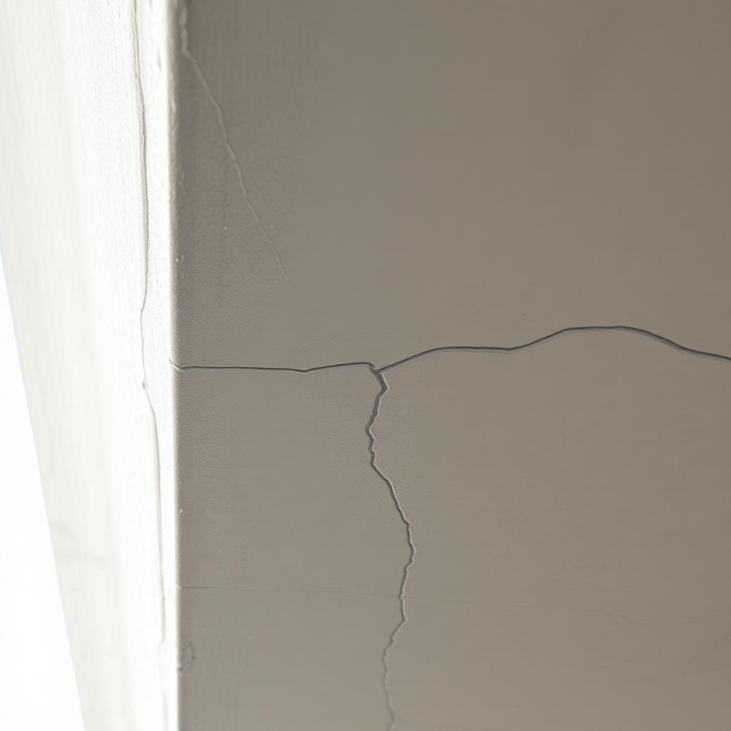
Hairline cracks

Tension-face cracks
Fig. 24.2Tension-face cracks

Fine cracks are OK; wide cracks are not.

§24.6.3

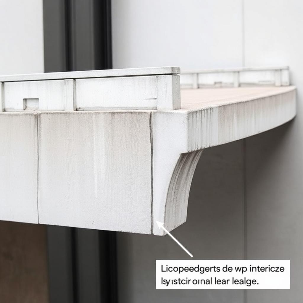
Creep sag

Balcony droop
Fig. 24.3Balcony droop

Long-term λΔ can double Δimm.

§24.6.4

Wide cracks

Structural cracks
Fig. 24.4Structural cracks

Crack width > 0.016 in triggers durability concerns.

10

Worked examples

Full textbook solutions — problem, theory, step-by-step, verification, interpretation

Example 24.1

Δimm and L/360 check for a 20-ft floor beam

Compute immediate deflection and compare to ACI Table 24.2.2 limit.

Problem statement

Simply supported RC beam, L = 20 ft, wservice = 1.5 k/ft. From cracked-section analysis Ie = 3,500 in⁴, Ec = 3,600 ksi. Check L/360 limit.

Long-span RC floor
FIG. 24.1 — Δimm is the visible sag at service load.
ΔSimply supported beam, w = 1.5 k/ft
DIMΔmax = 5wL⁴/(384·Ec·Ie).
Given
  • L = 20 ft
  • w = 1.5 k/ft
  • Ec = 3,600 ksi
  • Ie = 3,500 in⁴
Find
  • Δimm and L/360 pass/fail
Assumptions
  • Simply supported
  • Serviceability = unfactored loads
Code references
  • ACI 318-19 24.2
  • ACI Table 24.2.2
Theory & approach

Serviceability uses unfactored w. Ie is Branson's blend of Ig and Icr — no factored loads.

Step-by-step solution
  1. 1

    Convert units

    L = 20·12 = 240 in
    w = 1.5·1000/12 = 125 lb/in
    Ec = 3,600 ksi = 3.6×10^6 psi
  2. 2

    Formula

    FormulaMechanics
    Δ_imm = 5·w·L^4 / (384·Ec·Ie)
  3. 3

    Numerator

    240^4 = 3.318 × 10^9
    5·125·3.318×10^9 = 2.074 × 10^12
  4. 4

    Denominator

    384·3.6×10^6·3,500 = 4.838 × 10^12
  5. 5

    Δimm

    Δ = 2.074×10^12 / 4.838×10^12 = 0.429 in
  6. 6

    L/360 limit

    L/360 = 240/360 = 0.667 in
    0.429 < 0.667 → OK
Verification

Immediate deflection Δimm well under L/360. Long-term check still required.

Final answer
Δimm = 0.43 in ≤ L/360 = 0.67 in — OK.
Common mistakes
  • Using factored w (LRFD).
  • Mixing ksi and psi in Ec.
  • Using Ig instead of Ie.
References
  • · ACI 318-19
11

Guided practice

Compute the governing variables — hints unlock as you need them

A rectangular beam has I_g = 6,000 in⁴, I_cr = 2,000 in⁴, M_cr = 25 k·ft and service M_a = 100 k·ft. Compute the effective moment of inertia I_e (Branson's equation, ACI §24.2.3.5) and comment on which limit — cracking or full-section stiffness — dominates.

Your turn
Hints
  1. 1.Branson: I_e = (M_cr/M_a)³·I_g + [1 − (M_cr/M_a)³]·I_cr ≤ I_g.
12

Independent practice

Solve the chapter's design task — compute each governing variable

Design task

Compute the tension development length ld of a bottom #7 Grade-60 bar in normal-weight concrete with f'c = 4000 psi using the ACI 318 simplified basic equation ld/db = fy·ψt·ψe·ψs / (25·λ·√f'c).

Given
  • Bar: #7 (db = 0.875 in)
  • fy = 60,000 psi, f'c = 4000 psi
  • ψt = 1.0 (bottom bar), ψe = 1.0 (uncoated), ψs = 1.0 (#7 and larger)
  • λ = 1.0 (NWC)
Approach
  1. Substitute the modification factors first — all equal 1.0 here.
  2. ld/db = 60,000 / (25·1.0·√4000).
  3. ld = (ld/db)·db. Compare to the 12-in minimum in ACI 318 §25.4.2.4.
Submit your answer
13

Mini design challenge

Select the option that satisfies every code and serviceability requirement in the brief

Brief

A 20-ft simply-supported floor beam carries w_service = 1.5 k/ft with sustained fraction 60 %. Select the beam depth (h = 16, 18, 22, or 26 in) that satisfies BOTH the immediate live-load limit Δ_i,LL ≤ L/360 AND the incremental long-term deflection limit Δ_LT ≤ L/480 (attached-to-nonstructural), or invoke the ACI Table 9.3.1.1 min-h exemption.

Requirements
  • Compute I_e via Branson (ACI §24.2.3.5) with M_cr and M_a from the service load
  • Immediate LL deflection Δ_i,LL ≤ L/360 = 20·12/360 = 0.67 in (ACI Table 24.2.2)
  • Long-term multiplier λ_Δ = 2.0 for 5+ years, ρ' = 0
  • Incremental Δ_LT = λ_Δ·Δ_i,sustained + Δ_i,LL ≤ L/480 = 0.50 in
  • Alternative: use ACI Table 9.3.1.1 min-h = L/16 = 15 in to waive deflection calc
Section
Wt (lb/ft)
Δ (in)
Ru/Rn
Cost
Pick
14

Chapter summary

A mind map of how every concept connects

Graded Chapter Quiz(8 FE-style questions · ACI 318-19 required)

These questions reference ACI 318-19 — sections, equations, and tables are cited explicitly. Use a calculator. Each question offers a clue you may reveal before answering. Submissions are recorded to your account once signed in.

RC24-1ACI 318-19 Table 9.3.1.1
1. ACI minimum thickness for a simply supported normal-weight beam, Gr 60, L = 24 ft (span/16):
Serviceability · Δ ≤ L/360 Δ L
RC24-2ACI 318-19 §24.2.3.5
2. Effective moment of inertia Ie (Branson) at service moment Ma greater than Mcr:
RC24-3ACI 318-19 §24.2.4.1.1
3. Long-term multiplier λΔ for sustained load, 5+ years duration, no compression steel:
RC24-4ACI 318-19 Table 24.2.2
4. Deflection limit for a floor supporting non-structural elements likely to be damaged, sustained load part of Δ (McCormac Table 6.1 / ACI Table 24.2.2):
Serviceability · Δ ≤ L/360 Δ L
RC24-5ACI 318-19 §24.2.3.5
5. Ma = 60 ft-k, Mcr = 40 ft-k, Ig = 15,000 in⁴, Icr = 5,000 in⁴. Ie ≈ ?
RC24-6ACI 318-19 §24.2.4
6. Long-term deflection ΔLT if immediate live-load Δi,L = 0.30 in and sustained (DL) immediate Δi,D = 0.40 in, λΔ = 2.0:
Serviceability · Δ ≤ L/360 Δ L
RC24-7ACI 318-19 §24.3.2, Eq. 24.3.2
7. Crack-control maximum bar spacing (fs ≈ ⅔ fy = 40 ksi, cc = 2 in):
RC24-8ACI 318-19 §24.2.3
8. The primary purpose of the effective moment of inertia Ie is to:

Upload your worked solution (PDF)

Attach your handwritten or typed step-by-step solution for this chapter's graded quiz. The instructor can download every submission. PDF only, up to 25 MB.

How your upload will be graded

Your file — PDF, Word document, scanned handwriting or a photo — is read page by page like an experienced structural engineering instructor would. The scan is validated first, then your reasoning, structural model, calculations, diagrams, code basis and final answers are graded on process, not just the final number. Design work is additionally reviewed against AISC 360-22 and ACI 318-19. Partial credit applies, and one early mistake carried correctly forward is only penalized once.

Before you attach the file
  • Include every page, in order and right way up — a missing page cannot earn credit.
  • Keep margins in frame: nothing cropped at the edges, especially boxed final answers.
  • Scan or photograph in good, even light — no shadows, glare or blur; 300 dpi or a steady phone scan.
  • Write in dark pen; faint pencil is the most common 'UNREADABLE — INSTRUCTOR REVIEW REQUIRED' flag.
  • Include all diagrams, FBDs, shear/moment diagrams and section sketches — label them.
  • Number each question the same way the assignment does, and note anything you skipped.
  • Show units on every line and box your final answers.
  • Combine everything into ONE file (PDF preferred; Word, JPG or PNG accepted) under 20 MB.
Sign in to upload your worked solution.
16

FE exam preparation

NCEES-style practice with timer, equation sheet, and mastery tracking

Exam mode
30:00 Calculator
Question 1 / 10

λΔ for 5+ years with ρ' = 0 is:

◆ EasyACI 24.2.4.1