Bolted Connections
Bolt shear, bearing, tearout, slip-critical (Chapter J).
- AISC 360-22 §J3 — Bolts and Threaded Parts
Lecture Notes
This module introduces bolted connections. Lecture content here covers the governing physics, LRFD philosophy, and how the relevant AISC 360-22 chapter organizes the limit states.
Instructors can replace this text in Admin Mode. Each section is structured around: (1) behavior, (2) failure modes, (3) AISC limit-state equations, (4) design workflow, (5) detailing requirements.
A short comparison to ASD is included only where the resistance factor / safety factor relationship clarifies the LRFD design check.
Every chapter's worked example is one step in the design of the same building: Plan: 4 bays N–S × 3 bays E–W, each 30 ft × 30 ft. Stories: 4 @ 13 ft (52 ft roof). Composite floor: 4.5 in NW concrete on 3 VLI20 deck. Roof: 1.5 in B-deck + insulation + membrane. Materials: Wide-flange members A992 (Fy = 50 ksi, Fu = 65 ksi). Plates A572 Gr. 50. HSS bracing A500 Gr. C. Bolts A325-N 7/8 in dia. Welds E70XX. Concrete f'c = 4 ksi. Anchor rods F1554 Gr. 36.
Formula Sheet
| Name | Equation | AISC Ref |
|---|---|---|
| Bolt shear | φRn = 0.75 · Fnv · Ab | AISC §J3.7 |
| Bearing | φRn = 0.75 · 2.4 · db · t · Fu | AISC §J3.11 |
| Tearout | φRn = 0.75 · 1.5 · lc · t · Fu | AISC §J3.11 |
Worked Example
Bolted Connections
- Limit state 1
- Limit state 2
- 1. Required strengthCompute Ru.
- 2. Trial sectionPick a trial from AISC shape tables Instructor should verify with official AISC Manual.
- 3. Check each limit stateApply φ Rn ≥ Ru for every governing limit state.
- 4. IterateResize until the most economical section satisfies all checks.
- Skipping a limit state
- Using the wrong φ factor
- Forgetting serviceability checks
FE-Style Worked Examples (7)
Each example mirrors the NCEES FE Civil Reference Handbook style: brief givens, a labeled figure, AISC section reference, step-by-step numeric solution, and a single boxed answer.
- φRn0.75 × 54 × 0.442 = 17.9 k per shear plane
Textbook — Aghayere & Vigil (2009)(5 worked examples with figures + numerical answers)
Worked examples scanned directly from the CEGR 436 course textbook. Each card shows the original page (figure + full step-by-step solution) and adds an FE-style numerical multiple-choice prompt with answer key.
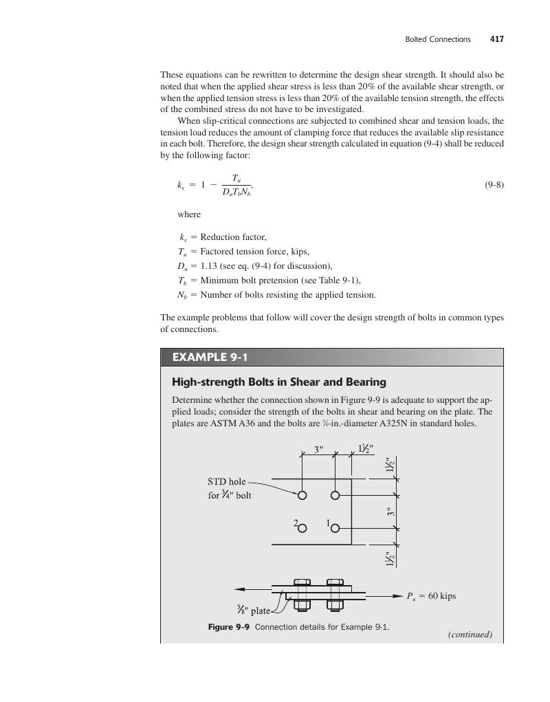
Chapter 9 develops bolt mechanics. A bolt may fail in (a) shear of the bolt body, (b) bearing of the plate against the bolt, (c) tearout of plate material to the edge, (d) tension of the bolt body, or (e) slip in a slip-critical joint. AISC §J3 governs.
- Bolt shear strength: φRn = 0.75·Fnv·Ab; Fnv = 54 ksi (A325 N), 68 (A325 X), 68 (A490 N), 84 (A490 X).
- Bearing on plate: φRn = 0.75·2.4·db·t·Fu (deformation OK at service).
- Tearout: φRn = 0.75·1.5·lc·t·Fu where lc = clear edge/spacing distance.
- Min spacing s ≥ 2 2/3·db (preferred 3·db); min edge per Table J3.4.
- Slip-critical (Class A): φRn = 1.00·μ·Du·hf·Tb·ns (μ = 0.30 Class A).
- Combined shear + tension: use elliptical interaction (§J3.7).
FE Practice Bank (1)
Multiple-choice problems pulled from the instructor's CEGR 492 FE Review packet (EasyFEExam © 2025, Steve Efe, PhD). Pick an answer, then click Reveal solution.
Interactive Calculator
Bolt Shear / Bearing / Tearout
AISC §J3.7, §J3.11Practice Problems
- [E] State φ for bolt shear (0.75).
- [E] Compute Ab for a 7/8 in. bolt.
- [E] State Fnv for A325-N (54 ksi) and A325-X (68 ksi).
- [E] State bearing equation φRn = 0.75·2.4·db·t·Fu.
- [E] Compute dh for a 1 in. bolt in a standard hole.
- [M] 3/4 in. A325-N in single shear. Compute φRn shear.
- [M] Bearing on 1/2 in. A36 plate at 7/8 in. bolt with edge dist. 1.5 in. Compute bearing + tearout.
- [M] Connection of 6 bolts 3/4 A325-N in double shear. Compute design strength.
- [M] Eccentric shear in a 6-bolt group, e = 4 in. — use Table 7-7 IC method.
- [M] Slip-critical: 3/4 A325, Class A μ = 0.30. Compute φRn per §J3.9.
- [H] Design beam-to-column shear-tab connection for Vu = 80 k using 3/4 A325-N bolts.
- [H] Combined shear + tension on a single 7/8 A325-N bolt: Vu = 12 k, Tu = 18 k. Check §J3.7.
- [H] Pretensioned 1 in. A490 with calibrated wrench. Verify per Table J3.1.
- [H] Design an oversized-hole connection (1/4 in. larger) and state when slip-critical is REQUIRED.
- [H] Investigate a 6-bolt single-shear lap splice that fails at 0.75 expected capacity. Identify likely cause.
- Bearing controls only when edge distance or pitch is tight.
- Slip-critical required for oversized/short-slotted holes loaded perpendicular to slot.
- Combined V+T: use Eq. J3-3a/3b.
- AISC 360-22 §J3
- AISC Manual Tables 7-1 to 7-7
Quiz (1 FE-bank + 2 concept)
Common Student Mistakes
- Mixing ASD and LRFD load combinations in the same problem.
- Using nominal strength Rn instead of design strength φRn.
- Forgetting to check every limit state listed in the AISC chapter.
"Professor Explains" Script
Today we're talking about bolted connections. Think of this topic as one step in the LRFD workflow: identify the demand, identify the limit states from the relevant AISC chapter, then check that φ·Rn is at least equal to Ru. We'll walk through the failure modes, the equations, and a worked example. Pay close attention to where the resistance factor changes — that's where students lose points on exams.