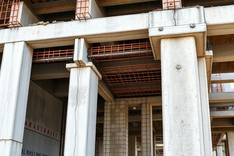
Fy and Fu — plus the right shape family — control every AISC calculation.
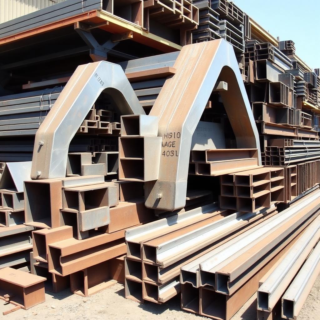
Chapter 3 covers ASTM specifications, the stress–strain curve, and the shape families (W, HP, HSS, angle, channel) that populate the AISC Shapes Database.
Iconic steel structures built on engineering excellence
What you will be able to do after finishing Chapter 1 — and why each objective matters in practice
Objective 01
Specify the right ASTM grade
A992 (Fy=50, Fu=65) is the standard for rolled W-shapes; A500 Gr. C for HSS; A36 for plates and angles.
Why it matters
Wrong grade = wrong Fy = wrong capacity.
Where it is used
Every AISC calc.
Connects to
AISC A3.1.
Objective 02
Read the stress–strain curve
E = 29,000 ksi elastic; yield plateau at Fy; strain-hardens to Fu; ruptures at ~15-25% strain.
Why it matters
Ductile steel warns before failure — brittle steel does not.
Where it is used
Plastic design, seismic detailing.
Connects to
Mechanics of materials; A3.
Objective 03
Navigate shape families
W (flexure), HP (piles), HSS (columns/braces), L (tension), C/MC (secondary).
Why it matters
The right family halves the material weight.
Where it is used
Preliminary sizing.
Connects to
AISC Manual Part 1.
Objective 04
Look up section properties
For each shape: A, d, bf, tf, tw, Ix, Iy, Sx, Sy, Zx, Zy, rx, ry, J, Cw.
Why it matters
AISC formulas plug these directly.
Where it is used
Every strength and stiffness check.
Connects to
AISC Manual Part 1.
Objective 05
Fracture toughness and CVN
Charpy V-Notch impact tests screen brittle behaviour at low temperature; AISC-Seismic requires demand-critical welds to satisfy CVN targets.
Why it matters
Brittle fracture is sudden and total.
Where it is used
Cold-region and seismic design.
Connects to
AISC Seismic A3.4.
Objective 06
Durability & corrosion
Painted, galvanised, or weathering steel (A588). Loss of section from corrosion reduces Ag and Fy relevance.
Why it matters
50-year service demands corrosion strategy from day 1.
Where it is used
Exposed structures, bridges.
Connects to
AISC/SSPC guidance.
03
Engineering motivation
What each part of a steel-frame building actually does — and why it exists
Before you design any single member, you have to see the whole system. A steel-frame building is not a collection of independent shapes bolted together — it is a deliberate load path, engineered so that every kilonewton of gravity, wind, or seismic demand has a continuous route from where it starts to the ground where the earth can resist it.
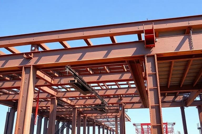
The photograph below shows a typical steel framing detail. Drag each labelled chip onto the structural element it names — the drop is only accepted when it lands inside the correct element's outlined region. A correct answer locks in with a green outline and a short explanation; a wrong answer flashes the region red, tells you what you actually hit, and returns the chip so you can try again. Press Reveal expected placements to see the reference solution (that attempt is then marked as assisted).
Fig. 1.3 · Drop a chip inside the outlined element it names. Green = correct and locked; red flash = wrong element, chip returns.
04
Failure mechanisms
Why we design the way we do — six ways steel structures have failed, and what each disaster taught the profession
Every provision in AISC 360 is a scar. Behind each equation, load factor, and detailing rule is a bridge, a walkway, or a tower whose failure cost lives and rewrote the profession. The six case studies below trace the mechanisms that motivate the code you are about to learn.
Read each one as an engineer, not a spectator: identify the load, the limit state, the missing check, and the specific clause that exists today because that check was missed. When you meet those clauses again in Chapters 5–17, they will read as answers, not rules.
Case 01
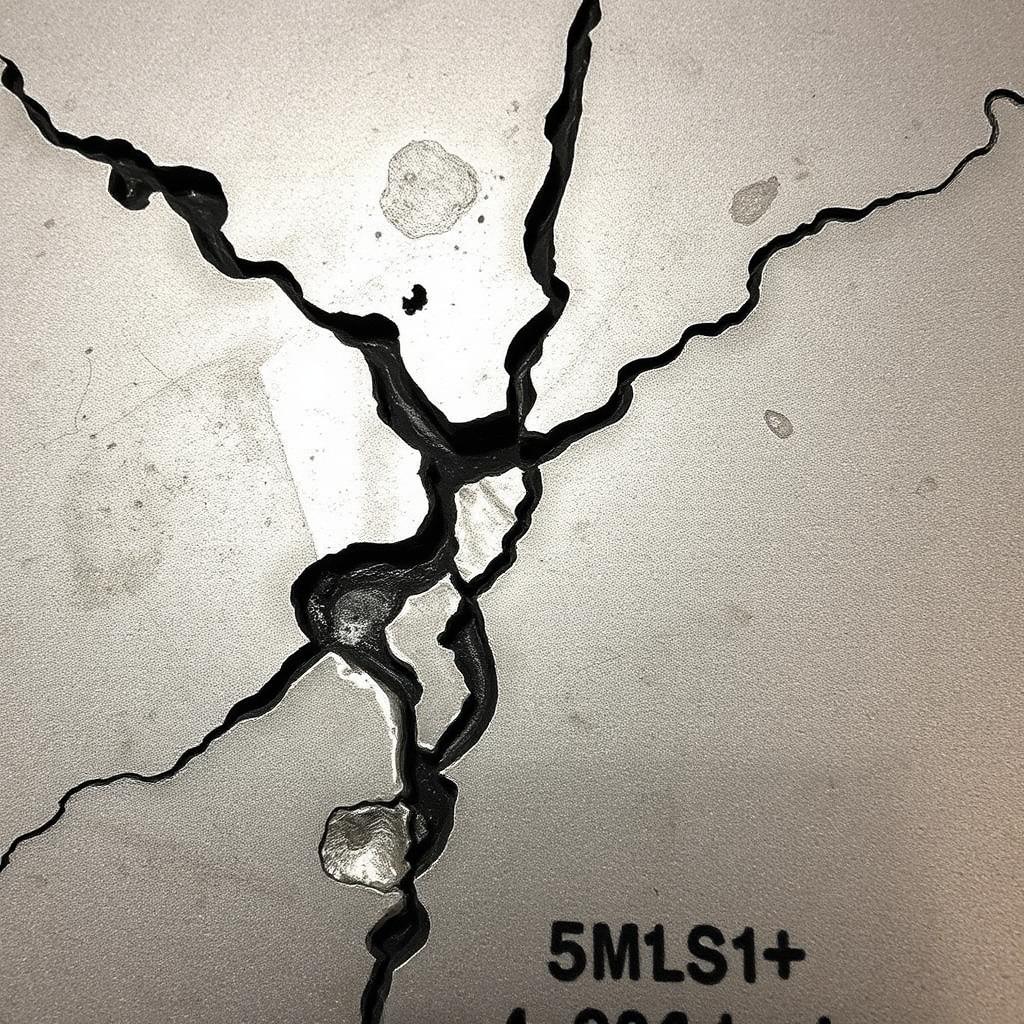
Fig. 1.4.1 · Brittle fracture
Failure mechanism
Brittle fracture
Cold-temperature cleavage fracture with little plastic warning.
Root cause
Low toughness, notch, tri-axial restraint.
Lesson learned
Specify CVN toughness for demand-critical welds; avoid sharp re-entrant corners.
§AISC 360-22 A3.1c / AISC Seismic
Case 02
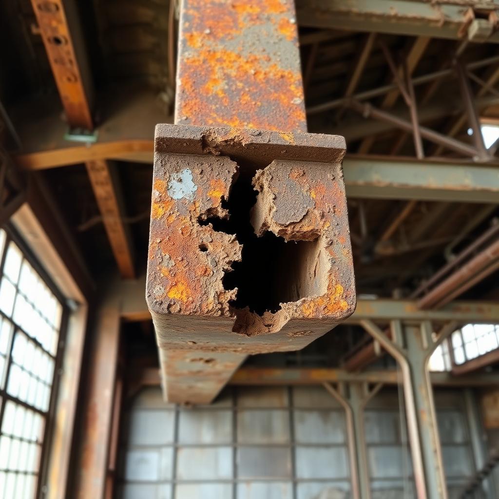
Fig. 1.4.2 · Corrosion / section loss
Failure mechanism
Corrosion / section loss
Rust reduces effective Ag and creates local pits.
Root cause
Water + oxygen + no coating.
Lesson learned
Paint, galvanise, or use weathering steel; inspect on schedule.
§SSPC / AISC durability
How failure propagates
The five-stage failure progression
1Mill cert
2Elastic response
3Yield plateau
4Strain hardening
5Rupture
Design codes intervene at the transition from yield to instability. Everything before yield is elastic and reversible; everything after instability is a race to collapse. LRFD keeps the demand well below the first transition.
05
Lecture notes
The full textbook chapter — figures, equations, and engineering narrative
Reflection · Think before you read
Two beams have identical geometry but one is A36 and the other is A992. Before running any numbers, where do you expect their behavior to differ — yielding, deflection, ductility, weldability, cost?
Structural materials: families, properties, and choosing one
Structural design is the planned organization of materials and components to safely resist internal and external forces — dead, live, and environmental loads — without exceeding strength or serviceability limit states. Choosing the right material means balancing strength, stiffness, durability, weight, and economy for the specific load path, exposure, and budget in front of you.
Structural steel
AISC 360-22 / AISC 341
• Ductile: yields visibly and redistributes force before fracture.
• Members are prefabricated — dimensional control and shop QA are excellent.
• Loses ~50% of yield strength near 1100 °F; needs spray-on or board fireproofing.
Reinforced concrete
ACI 318-19
• Monolithic construction gives inherent continuity and redundancy.
• Design is under-reinforced on purpose so steel yields first (ductile warning).
• Self-weight is often 60–70% of total gravity load in a concrete frame.
Timber / mass timber
NDS / AWC
• Renewable and carbon-storing — strongest sustainability case of the six.
Fire protection required; stability (LTB, local buckling) governs often
Cracking/deflection serviceability; heavy seismic mass; long cure schedule
Moisture content, shrinkage, connection crushing, char rate in fire
Specialty mixing/curing; limited local supply; few prescriptive code provisions
Brittle in seismic shear unless reinforced and grouted; out-of-plane loading
Brittle failure — design with large strength-reduction factors; bond/debonding controls
Governing code
AISC 360-22 / AISC 341
ACI 318-19
NDS / AWC
ACI 239 / AASHTO UHPC guidance
TMS 402/602
ACI 440.2R / 440.11
How engineers actually make the choice
Load path & stress type
Trace the force to the foundation first. Tension and long spans favor steel or FRP; sustained compression and bearing favor concrete or masonry; light gravity framing favors timber.
Stiffness & serviceability
Strength rarely governs slender systems — deflection, drift, and floor vibration do. Compare EI and mass before choosing, not after sizing.
Environmental exposure
Assess humidity, freeze-thaw cycling, de-icing salts, and industrial chemicals. Corrosive exposure pushes toward concrete cover, galvanizing, UHPC, or FRP reinforcement.
Fire and life safety
Concrete and masonry are inherently rated; steel needs applied protection; timber relies on sacrificial char depth; FRP resins soften early.
Budget & constructability
Balance first cost against maintenance, formwork, crane access, schedule, and the skill available in the local labor market.
Steel for long spans and tension. Concrete for heavy static compression, fire, and water. Timber for light, low-carbon framing. Masonry for bearing and shear walls with thermal mass. UHPC for thin, aggressive-exposure elements. FRP for corrosion-driven retrofits — never as the sole source of ductility.
Worked Example 3.1 — Material Properties from a Tension Coupon Test
Given: An ASTM A992 tension coupon has a gauge length Lo = 8.00 in and cross-sectional area Ao = 0.500 in². Selected data from the pull test:
At P = 12.0 k the elongation ΔL = 0.00662 in (still elastic).
Upper yield load Py = 25.5 k.
Ultimate load Pu,max = 32.8 k at ΔL = 0.72 in.
After unloading from a point at ΔL = 0.048 in, permanent set = 0.040 in.
A parallel 0.2% offset line intersects the curve at σ = 51.2 ksi.
Step 7 — Why do Sx, Zx, and the shape factor matter?
Design relevance of each quantity:
Elastic section modulus Sx pins down the first-yield moment My = Fy·Sx. Below My the whole section is elastic and the σ = M·c/I formula applies — Sx is what you use in serviceability (deflection, fatigue, elastic bending stress) checks.
Plastic section modulus Zx gives the fully-plastic moment Mp = Fy·Zx, the strength AISC 360-22 §F2 uses for the LRFD design moment φbMn of a compact, laterally-braced beam. Zx — not Sx — is the number tabulated in Manual Table 3-2 and the value you compare demand to when sizing a beam.
Shape factor f = Zx/Sx measures the reserve strength between first yield and full plastification: (Mp − My)/My = f − 1. For this built-up I, f = 1.12 → 12% reserve above first yield. Values ≈ 1.10–1.15 for W-shapes, 1.5 for rectangles, 1.7 for solid rounds; the higher the shape factor, the more inefficient the section is at putting material near the extreme fibre.
Why LRFD design uses Mp, not My. A compact section can develop the plastic moment before local buckling; stopping the strength check at My would waste roughly (f − 1)·100 % of the section's capacity. That is why AISC anchors the flexural design equation on Zx.
Sanity check. If your computed f falls outside 1.10–1.20 for a W-shape or built-up I, something in the Sx/Zx calculation is wrong — usually a c = d/2 slip in Sx or a missed web-half in Zx.
Common pitfalls:
Confusing 0.2% offset yield (a construction on the σ–ε plot) with the upper/lower yield point. Only steels without a sharp plateau require the offset method.
Using the web clear height (11 in) instead of the full depth (12 in) when computing c = d/2 for Sx.
Forgetting that for a doubly-symmetric section the PNA and elastic N.A. coincide — for singly-symmetric sections you must locate the PNA by equal-area split before computing Z.
Reporting Sx and Zx without checking that the shape factor lands in the expected 1.10–1.20 range for I-shapes (sanity check).
06
Professional practice, safety & ethics
Material specification practice
Professional practice
•Specify by ASTM designation and grade (A992 for W-shapes, A500 Gr. C for HSS, A572 Gr. 50 for plate) — never by 'Fy = 50 ksi' alone.
•Require Mill Test Reports (MTRs) for all primary members and verify heat numbers against the shipment.
•Check availability before specifying an exotic grade; substitution requests delay fabrication.
Safety in design & construction
•Notch toughness (CVN) matters for thick plate, cold service, and seismic applications — specify it where fracture is credible.
•Galvanizing thick weldments can cause cracking; coordinate the coating and welding sequence.
•Fire protection is a material issue: unprotected steel loses ~50% of Fy near 1100 °F.
Engineering ethics
•Unapproved material substitution to save cost, without EOR review, is a serious violation.
•Never accept material without traceable documentation — counterfeit MTRs have appeared in the supply chain.
•Report suspect material to the client and building official (NSPE II.1.a).
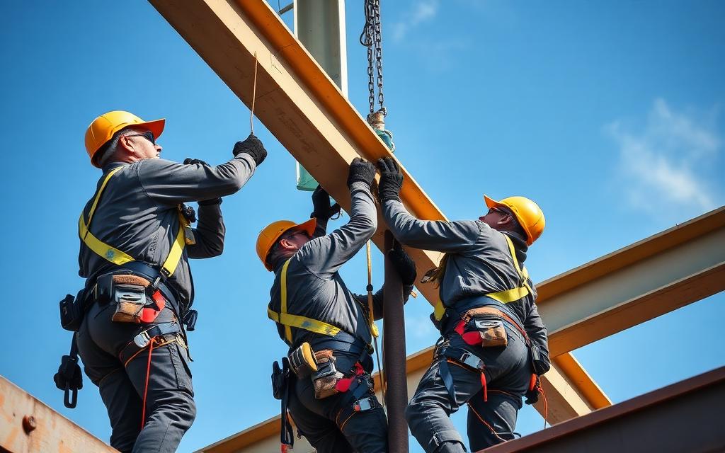
Erection safety: OSHA Subpart R fall protection and stable temporary bracing.Peer review and the engineer's seal: responsible charge and standard of care.
ABET / licensure link. These points map to ABET Student Outcomes 2 and 4 — engineering design within realistic constraints, and recognition of ethical and professional responsibilities. Expect NCEES FE and PE exam questions on the NSPE Code of Ethics, OSHA construction requirements, and the engineer's standard of care.
07
Cost analysis
Grade and shape selection economics
Approach
•Higher-strength steel (A992 Gr. 50 vs A36) costs only a few percent more per pound but can cut 20–30% of the weight in strength-governed members.
•Strength grades do not help stiffness-governed members — E is the same for all steels.
•Availability drives price: use common shapes and grades; exotic sections carry mill minimums and lead time.
Worked cost example — A36 vs A992 for a strength-governed tension member
Basis: Same required φPn = 300 kip
Line item
Qty
Rate
Cost
A36 section, Ag = 9.3 in² (31.6 lb/ft, 30 ft)
0.47 ton @ A36
$1,080
$508
A992 section, Ag = 6.7 in² (22.5 lb/ft, 30 ft)
0.34 ton @ A992
$1,150
$391
Fabrication saved (lighter piece)
-0.13 ton
$900
−$117
Estimated total
$782
Takeaway. The 50 ksi option is lighter and cheaper installed even at a higher $/ton — always price the installed member, not the coupon.
Unit rates are representative US averages for teaching purposes. On a real project, price with current local rates (RSMeans, fabricator quotes, or contractor pricing) and state the estimate date.
08
Animated concepts
Key mechanics visualised — watch the strain profile, stress block, or buckled shape evolve
Full-page reference diagrams — the visual vocabulary you will use for the rest of the course
§3.6.1
Shape yard
Fig. 3.1W, HSS, L, C stacked
Match the family to the loading.
§3.6.2
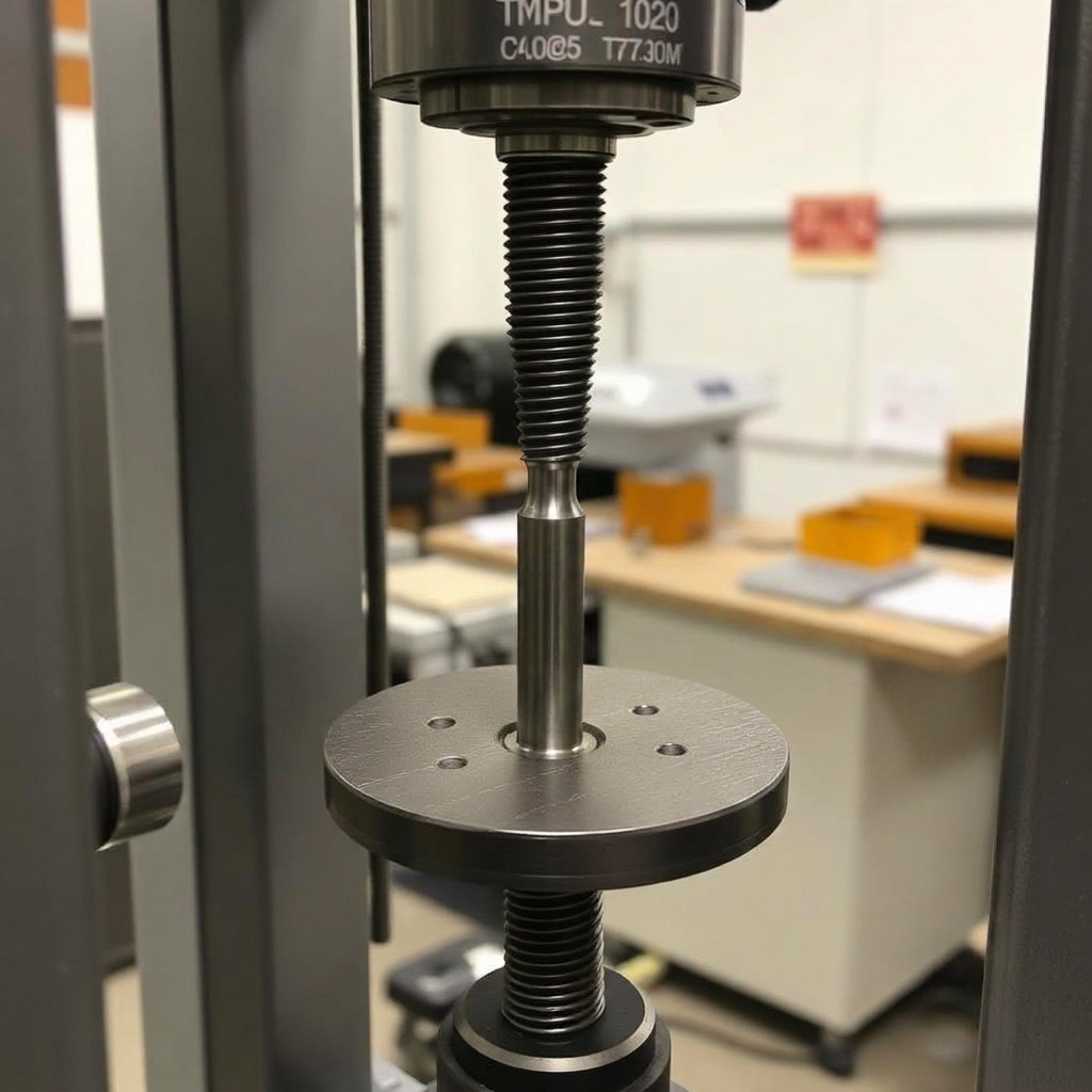
Tensile test
Fig. 3.2Coupon in UTM
Yield → strain-hardening → rupture.
§3.6.3
Brittle fracture
Fig. 3.3Cleavage surface
Little plastic warning.
§3.6.4
Corrosion
Fig. 3.4Section-loss beam
Coating is a design decision.
10
Worked examples
Full textbook solutions — problem, theory, step-by-step, verification, interpretation
Example 3.1
W14x90 (A992) — properties and shape factor
Lookup Fy, Fu, Sx, Zx from the AISC Manual and compute the shape factor.
Problem statement
Confirm ASTM properties and section properties for a W14x90 (A992), then compute its shape factor Zx/Sx.
FIG. 3.1 — the AISC Shapes Database is your first stop.DIMW-shape geometry — d, bf, tf, tw drive every section property.
Given
W14x90 (A992)
AISC Manual Part 1
Find
Fy, Fu, Sx, Zx, Zx/Sx
Assumptions
Rolled, mill-certified shape
Room-temperature
Code references
ASTM A992
AISC Manual Part 1
Theory & approach
The shape factor bounds the plastic reserve above elastic Sx. For rolled W-shapes it is typically 1.10–1.15.
Step-by-step solution
1
ASTM lookup
FormulaASTM A992
Fy = 50 ksi, Fu = 65 ksi
2
AISC Manual Part 1
W14x90: Ag = 26.5 in², Sx = 143 in³, Zx = 157 in³, rx = 6.14 in, ry = 3.70 in
3
Shape factor
Formula
SF = Zx / Sx
SF = 157 / 143 = 1.10
Final answer
Fy=50, Fu=65 ksi; Sx=143, Zx=157 in³; SF=1.10.
Common mistakes
Using A36 Fy=36 for a W-shape.
Confusing Sx (elastic) with Zx (plastic).
References
· ASTM A992
· AISC Manual 16th ed. Part 1
11
Guided practice
Compute the governing variables — hints unlock as you need them
Identify the specified minimum yield stress F_y and tensile stress F_u for (a) an A500 Grade C round HSS and (b) an A992 W-shape. State the modulus of elasticity E and comment on whether E differs between grades.
Your turn
Hints
1.Look up A500 Gr. C round HSS in AISC Manual Table 2-4: F_y = 46 ksi, F_u = 62 ksi.
12
Independent practice
Solve the chapter's design task — compute each governing variable
Design task
For A992 structural steel (Fy = 50 ksi, Fu = 65 ksi, E = 29,000 ksi), compute the yield strain εy, the strain-hardening strain εsh ≈ 10·εy, and the flange local-buckling slenderness limit λr = 0.56·√(E/Fy) for a rolled I-shape flange.
Given
Fy = 50 ksi
E = 29,000 ksi
εsh ≈ 10·εy (typical for mild steel)
Approach
εy = Fy / E — the elastic strain at first yield.
For A992, εsh is not a code number; use 10·εy as the lecture approximation.
AISC Table B4.1b flange λr for rolled I-shapes: 0.56·√(E/Fy).
Submit your answer
13
Mini design challenge
Pick the shape family + ASTM grade that fits each application
Brief
Match the correct steel product/family AND specification to each application: 24-ft office floor beam, 12-ft interior gravity column, bolted single-angle brace diagonal, and a channel stair stringer. Cite AISC Manual Part 1 shape tables and Part 2 material tables.
Requirements
State the shape family (W, HSS, L, C)
State the preferred ASTM specification (Manual Table 2-4)
These questions reference AISC Steel Construction Manual (16th ed.) — sections, equations, and tables are cited explicitly. Use a calculator. Each question offers a clue you may reveal before answering. Submissions are recorded to your account once signed in.
C3-01AISC 360-22 §B4
1. Modulus of elasticity of structural steel (AISC 360-22 §B4) is:
C3-02AISC 360-22 §B4
2. Shear modulus G of steel:
C3-03ASTM A370
3. The 0.2% offset yield stress for a stress-strain curve reaching σ = 55 ksi at ε=0.005 (with slope 29,000 ksi through origin) is estimated by:
C3-04AISC Manual Table 2-4
4. For a W14×90 (A992), what is Fy per AISC Manual Table 2-4?
C3-05Mechanics of materials
5. Which is the 'plastic' modulus of a rectangular section b×h?
C3-06Mechanics
6. Centroid of a T-section (flange 6×1 in + stem 1×5 in, total depth 6 in from top of flange) measured from top:
C3-06BMechanics — parallel-axis theorem
7. For the same T-section (flange 6×1 in over stem 1×5 in, ȳ = 1.86 in from the top), compute the moment of inertia Ix about the horizontal centroidal axis:
C3-07Mechanics
8. For a rectangular 4×8 in section (b=4, h=8, weak axis: b), Ix (in⁴):
C3-08Mechanics
9. Elastic section modulus Sx for the section in C3-07:
C3-09Mechanics
10. Plastic section modulus Zx for the section in C3-07:
C3-10AISC Manual Part 1
11. Which shape offers the best flexural efficiency (highest Z/A) among these?
C3-11ASTM A36
12. A hot-rolled A36 flat has Fy=36 ksi, Fu=58 ksi. Minimum required elongation in 8-in gauge per ASTM A36:
C3-12AISC 360-22 §B4
13. Coefficient of thermal expansion α for steel used for expansion joints:
C3-13Mechanics of materials / AISC Manual Table 1-1 (compare)
14. For the welded W-shape shown (two flanges 7 in × 0.50 in, web 0.30 in thick, overall depth d = 16 in), compute Ix, Sx and Zx about the strong (x-x) axis by hand — locate the centroid, use the parallel-axis theorem for the flanges, then the plastic modulus. What is the shape factor Zx/Sx?
C3-14AISC 360-22 §B4 / Mechanics of Materials
15. Structural steel has E = 29,000 ksi and Poisson's ratio ν = 0.30. Compute the shear modulus G.
C3-15Mechanics of Materials
16. A stainless-steel alloy has E = 28,000 ksi and G = 10,769 ksi. Back-calculate Poisson's ratio ν.
C3-16Mechanics of Materials
17. A high-strength alloy reports E = 30,000 ksi and ν = 0.28. What is G?
C3-17Mechanics of Materials
18. A shaft twists under pure torsion with shear strain γ = 0.0012 rad when the shear stress is τ = 13.4 ksi. If ν = 0.30, estimate the axial modulus E of the material.
Attach your handwritten or typed step-by-step solution for this chapter's graded quiz. The instructor can download every submission. PDF only, up to 25 MB.
How your upload will be graded
Your file — PDF, Word document, scanned handwriting or a photo — is read page by page like an experienced structural engineering instructor would. The scan is validated first, then your reasoning, structural model, calculations, diagrams, code basis and final answers are graded on process, not just the final number. Design work is additionally reviewed against AISC 360-22 and ACI 318-19. Partial credit applies, and one early mistake carried correctly forward is only penalized once.
Before you attach the file
Include every page, in order and right way up — a missing page cannot earn credit.
Keep margins in frame: nothing cropped at the edges, especially boxed final answers.
Scan or photograph in good, even light — no shadows, glare or blur; 300 dpi or a steady phone scan.
Write in dark pen; faint pencil is the most common 'UNREADABLE — INSTRUCTOR REVIEW REQUIRED' flag.
Include all diagrams, FBDs, shear/moment diagrams and section sketches — label them.
Number each question the same way the assignment does, and note anything you skipped.
Show units on every line and box your final answers.
Combine everything into ONE file (PDF preferred; Word, JPG or PNG accepted) under 20 MB.
Sign in to upload your worked solution.
16
FE exam preparation
NCEES-style practice with timer, equation sheet, and mastery tracking
Q1 — An ASTM A36 structural steel plate is tested in tension. As force increases, the steel reaches a critical stress where it begins to permanently stretch and deform without any additional load. Which mechanical property marks this transition from elastic to plastic behavior?
 Objective 01