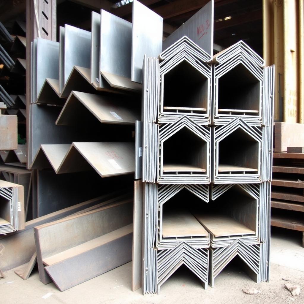
Shear does not care about Zx — it lives in the web.
For most rolled W-shapes, phi_v*Vn = 0.60*Fy*Aw. Everything else is web-slenderness bookkeeping.
Chapter 7 covers AISC 360-22 Chapter G: web shear yielding for non-slender webs (G2.1 with phi_v = 1.00 or 0.90), shear buckling for slender webs, tension-field action for plate girders, plus the AISC J10 concentrated-force checks (web yielding, web crippling, and side-sway).
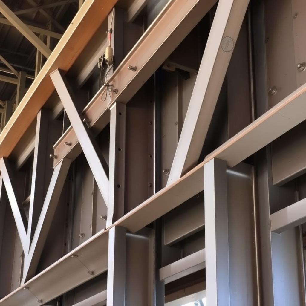
Iconic steel structures built on engineering excellence
What you will be able to do after finishing Chapter 1 — and why each objective matters in practice
Objective 01
Compute Vn = 0.6*Fy*Aw*Cv1 (G2.1)
For rolled I-shapes with h/tw <= 2.24*sqrt(E/Fy), Cv1 = 1.0 and phi_v = 1.00.
Why it matters
Most rolled W-shapes fall in this pocket — the shear check is one line.
Where it is used
Every gravity beam and girder shear check.
Connects to
AISC G2.1; Manual Table 3-2 phi_v*Vn column.
Objective 02
Classify web slenderness h/tw
h/tw versus 2.24*sqrt(E/Fy) (~53.9 for A992). Below: Cv1 = 1.0 with phi_v = 1.00. Above: Cv1 reduces and phi_v = 0.90.
Why it matters
The pocket determines phi and the buckling knock-down.
Where it is used
Deep W-shapes, plate girders, custom sections.
Connects to
AISC G2.1; Table B4.1b web limits.
Objective 03
Handle shear buckling / tension-field
For h/tw > 260 and stiffened webs, tension-field action (G2.2/G3) recovers strength beyond elastic buckling.
Why it matters
Plate girders would be uneconomic without tension-field capacity.
Where it is used
Plate girders in bridges and long-span roofs.
Connects to
AISC G2.2, G3; Basler theory.
Objective 04
Run J10 concentrated-force checks
Web local yielding (J10.2), web crippling (J10.3), sidesway web buckling (J10.4).
Why it matters
Reactions at supports and point loads under columns govern local web failures.
Where it is used
Every beam bearing on a column or wall; every point-loaded girder.
Connects to
AISC J10.
Objective 05
Read Manual Table 3-2 (phi_v*Vn)
Table 3-2 tabulates phi_v*Vn for every W in one column.
Why it matters
Fastest FE-exam shortcut.
Where it is used
Every design office; every FE shear question.
Connects to
AISC Manual Part 3.
Objective 06
Verify Aw = d*tw
For a W-shape, Aw is taken as the full depth times the web thickness.
Why it matters
Aw is not the clear web height — a common student error.
Where it is used
Every G2.1 calc.
Connects to
AISC G2.1(b).
03
Engineering motivation
What each part of a steel-frame building actually does — and why it exists
Before you design any single member, you have to see the whole system. A steel-frame building is not a collection of independent shapes bolted together — it is a deliberate load path, engineered so that every kilonewton of gravity, wind, or seismic demand has a continuous route from where it starts to the ground where the earth can resist it.
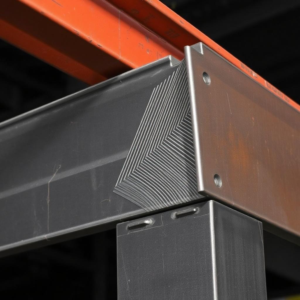
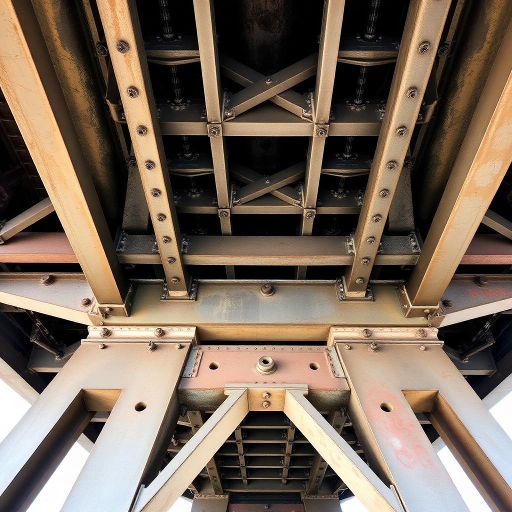
The photograph below shows a typical steel framing detail. Drag each labelled chip onto the structural element it names — the drop is only accepted when it lands inside the correct element's outlined region. A correct answer locks in with a green outline and a short explanation; a wrong answer flashes the region red, tells you what you actually hit, and returns the chip so you can try again. Press Reveal expected placements to see the reference solution (that attempt is then marked as assisted).
Fig. 1.3 · Drop a chip inside the outlined element it names. Green = correct and locked; red flash = wrong element, chip returns.
04
Failure mechanisms
Why we design the way we do — six ways steel structures have failed, and what each disaster taught the profession
Every provision in AISC 360 is a scar. Behind each equation, load factor, and detailing rule is a bridge, a walkway, or a tower whose failure cost lives and rewrote the profession. The six case studies below trace the mechanisms that motivate the code you are about to learn.
Read each one as an engineer, not a spectator: identify the load, the limit state, the missing check, and the specific clause that exists today because that check was missed. When you meet those clauses again in Chapters 5–17, they will read as answers, not rules.
Case 01
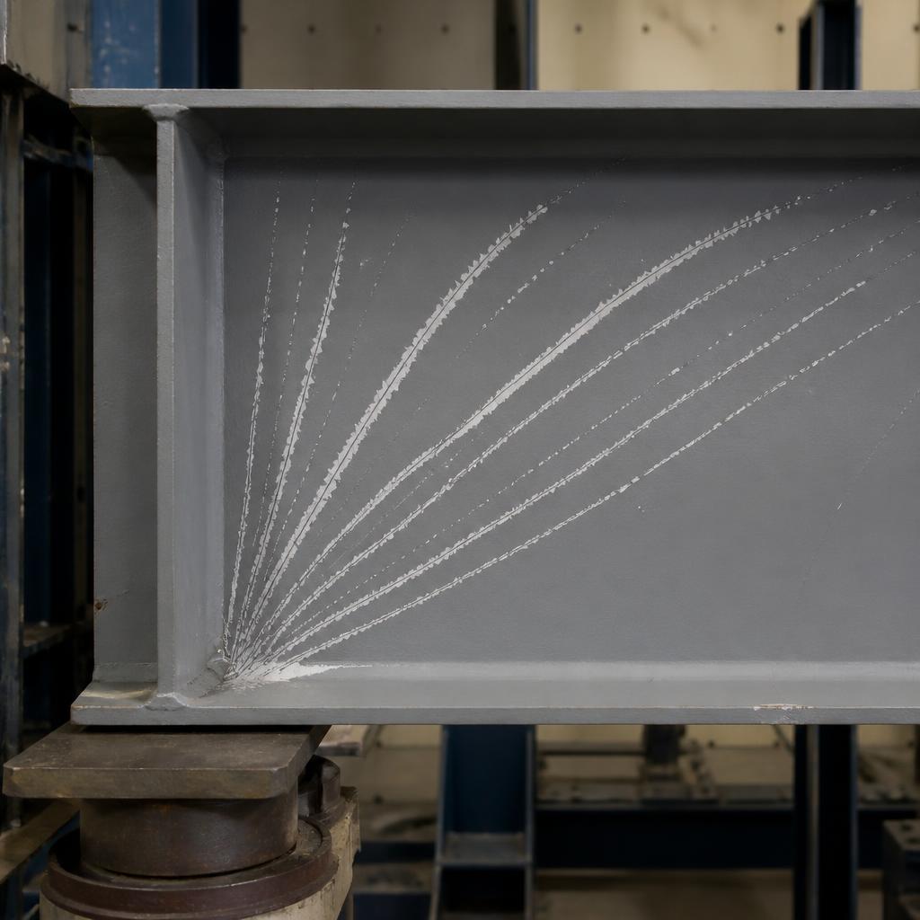
Fig. 1.4.1 · Web shear buckling
Failure mechanism
Web shear buckling
A slender web crinkles diagonally under shear before yielding.
Root cause
h/tw > 2.24*sqrt(E/Fy) triggers Cv1 < 1.0.
Lesson learned
Use G2.1 with Cv1 reduction, or add stiffeners and mobilise tension-field.
§AISC G2.1 / G2.2
Case 02
Fig. 1.4.2 · Web crippling
Failure mechanism
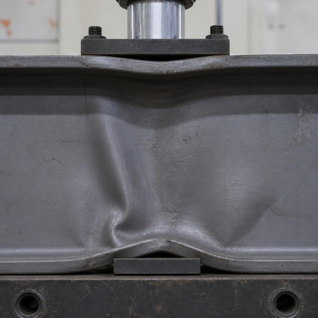
Web crippling
A concentrated load buckles the web locally at the bearing.
Root cause
N (bearing length) too short and web too thin; J10-4 or J10-5a.
Lesson learned
Use bearing plates or bearing stiffeners; check J10.
§AISC J10.3
Case 03
Fig. 1.4.3 · Web local yielding
Failure mechanism
Web local yielding
Web yields directly under a point load or reaction over a short bearing length.
Root cause
Rn = (2.5*k + N)*Fy*tw not satisfied.
Lesson learned
Increase N or add a bearing stiffener.
§AISC J10.2
How failure propagates
The five-stage failure progression
1Applied load
2Elastic shear
3Diagonal principal stress
4Web buckle
5Collapse
Design codes intervene at the transition from yield to instability. Everything before yield is elastic and reversible; everything after instability is a race to collapse. LRFD keeps the demand well below the first transition.
05
Lecture notes
The full textbook chapter — figures, equations, and engineering narrative
Reflection · Think before you read
For a typical rolled W-shape, flexure almost always governs — yet for short, deep beams and plate girders, shear can control. What geometric ratio flips that balance, and can you think of a real structure where it matters?
Chapter focus. Every beam that carries transverse load must transfer that load to its supports as shear, and every connection at a beam end is really a shear connection. Chapter G answers one deceptively simple question: how much shear can the web alone carry before it yields or buckles? For the vast majority of rolled W-shapes at Fy = 50 ksi the answer is almost trivial — φv = 1.00 and Vn = 0.6FyAw — but as webs get thinner and deeper (plate girders, built-up sections, channels, HSS), shear buckling, stiffener spacing, and coped-end block shear all become governing checks that a careless designer will miss.
1. Why the Web (Almost) Alone?
In an I-shaped beam under transverse load, elastic shear-flow theory (VQ/Ixt) shows the shear stress is parabolic through the depth and is concentrated almost entirely in the thin web; the flanges, being far from the neutral axis and oriented perpendicular to V, carry a negligible fraction (typically < 5%). AISC exploits this by ignoring the flange contribution altogether and using a single, conservative, uniform stress on a simplified web area Aw, rather than requiring a full elastic shear-flow calculation for every beam.
Figure 7.1 — Idealized shear-stress distribution in a W-shape: web carries essentially all of V; AISC replaces the true parabola with a uniform average stress over Aw.
2. The Web Shear Area, Aw
AISC's shear area is deliberately simple — the full section depth times the web thickness, not the clear distance between flanges (h) and not the gross area Ag. Using the full depth is a conservative simplification that already builds in margin for the small shear carried by the fillets/flange webs.
AISC 360-22 §G2.1(b)
(1)
Aw=d⋅tw
d = overall (nominal) depth of the section, in.
tw = web thickness, in.
Physically: a deeper, thicker web gives more Aw and more shear capacity — this is why deep, heavy beams rarely have a shear problem even when their moment demand is very high.
Figure 7.2 — Aw uses the full outside depth d, not the clear web height h. Do not confuse the two: h is only used to compute the slenderness ratio h/tw.
3. Nominal Shear Strength — Web Yielding vs. Web Shear Buckling (§G2.1)
A slender plate loaded in pure shear behaves just like a plate loaded in compression: if it is stocky it yields in shear; if it is thin it buckles diagonally before the shear yield stress 0.6Fy is reached. AISC captures both behaviors with a single equation and a web shear coefficient Cv1 that ranges from 1.0 (full yielding) down toward zero (very slender, elastic buckling).
Spec. Eq. G2-1
(2)
Vn=0.6⋅Fy⋅Aw⋅Cv1
Cv1 is found from the web slenderness ratio h/tw compared against two limits that depend on the plate-buckling coefficient kv (kv = 5.34 for unstiffened webs of most rolled shapes):
User Note shortcut (§G2.1(a)). For all standard rolled I-shapes with Fy ≤ 50 ksi that satisfy h/tw ≤ 2.24 √(E/Fy) (≈ 53.95 at Fy = 50 ksi), AISC simply sets Cv1 = 1.0 and gives the higher resistance factor φv = 1.00 (Ωv = 1.50) instead of the usual φv = 0.90 (Ωv = 1.67). Almost every rolled W-shape in the Manual at 50 ksi qualifies — this is why beam shear is so rarely a governing check in ordinary buildings.
Figure 7.3 — Cv1 as a function of web slenderness. Region 1: full shear yielding, φv = 1.00. Region 2: inelastic buckling, φv drops to 0.90. Region 3: elastic buckling (Eq. G2-4, not shown numerically here), Cv1 ∝ 1/(h/tw)².
4. Design (Available) Shear Strength
(5)
LRFD:ϕvVn≥Vu∣ASD:Vn/Ωv≥Va
Condition
φv (LRFD)
Ωv (ASD)
Applies to
h/tw ≤ 2.24√(E/Fy), rolled I-shape, Fy ≤ 50 ksi
1.00
1.50
Nearly all rolled W, S, HP shapes (§G2.1(a))
All other doubly-symmetric shapes / built-up girders
§G1(a) — the §G2.1(a) exception never applies to channels
Single angles
0.90
1.67
§G4
Round HSS
0.90
1.67
§G5, uses Fcr from torsional/shear buckling
Rectangular HSS / box sections
0.90
1.67
§G4/G2.1, Aw = 2ht (two webs)
Doubly-symmetric shapes, minor-axis shear
0.90
1.67
§G6, flanges act as the "web"
Common trap: the φv = 1.00 / Ωv = 1.50 pocket is a narrow exception, not the default. Channels, built-up girders, and minor-axis shear always use φv = 0.90 even when their h/tw is small.
5. Transverse Stiffeners and Tension-Field Action (§G2.2, §G3)
When a web is too slender to rely on Cv1 alone, transverse stiffeners can be added. Stiffeners do two things: (1) they raise the plate-buckling coefficient kv, effectively subdividing the web into shorter, stockier panels; and (2) for stiffened interior panels, AISC permits tension-field action (TFA) — post-buckling reserve strength in which the buckled web acts like the diagonal member of a Pratt truss, anchored by the stiffeners and flanges, developing shear far beyond the elastic buckling load. TFA is not permitted in end panels (no anchorage on one side) or when a/h > 3 or a/h > [260/(h/tw)]².
Figure 7.4 — Transverse stiffeners subdivide a slender web into panels of width a. Interior panels can mobilize a diagonal tension field; end panels (adjacent to a free edge/reaction) cannot.
Almost all AISC Manual rolled W-shapes never need stiffeners for ordinary gravity beams — this topic matters mainly for plate girders and deep built-up sections, developed further with worked stiffener-spacing design in Chapter 10.
6. Shear in Channels (§G1, §G2.1)
A channel has only one web, so Aw = d·tw exactly as for a W-shape, and the nominal strength equation (Eq. G2-1) is identical. The only difference is the resistance factor: per §G1(a), the φv = 1.00 / Ωv = 1.50 shortcut of §G2.1(a) applies only to I-shaped rolled sections — never to channels. Channels always use φv = 0.90, Ωv = 1.67, even though many rolled channels satisfy the same stocky-web slenderness limit.
7. Minor-Axis (Weak-Axis) Shear — §G6
Occasionally a member must carry shear parallel to its weak axis (e.g., a beam framing at 90° into a girder web, or wind load on a column oriented to bend about y). In that orientation, the two flanges are the "webs" resisting shear, each behaving like a rectangular plate in shear bending about its own weak axis; the actual web of the shape contributes negligibly.
Spec. Eq. G6-1
(6)
Vn=0.6⋅Fy⋅bf⋅tf⋅Cv2(perflange
multiplyby2forbothflanges)
Cv2 is computed the same way as Cv1 but using h/tw → bf/(2tf) and kv = 1.2 (per §G2.2, referenced from G6). Per the §G6 User Note, Cv2 = 1.0 for essentially all rolled W-, S-, M-, and HP-shapes at Fy ≤ 70 ksi.
Figure 7.5 — (a) Channel major-axis shear: single web area Aw = d·tw. (b) Minor-axis shear in a doubly-symmetric shape: both flanges act as parallel "webs" per §G6.
8. Coped Beam Ends: Block Shear and Local Section Checks (§J4.3, Manual Part 9)
When the top (or top and bottom) flange of a beam is trimmed away ("coped") to fit around a supporting girder flange, two new limit states appear that have nothing to do with Chapter G's uniform web-shear check: (1) block shear rupture of the bolted or welded connection region (a combined shear-yield/shear-fracture plane plus a perpendicular tension plane, per §J4.3 — the identical mechanics used for gusset plates and tension members), and (2) local buckling or flexural yielding of the reduced (coped) web section, checked using AISC Manual Part 9 procedures because the coped region is a short, deep cantilever stub with its own effective depth and slenderness.
Spec. Eq. J4-5 (block shear)
(7)
Rn=0.6FuAnv+UbsFuAnt≤0.6FyAgv+UbsFuAnt
Agv, Anv = gross/net area on the shear plane (vertical, through the bolt line).
Ant = net area on the tension plane (horizontal, from the last bolt to the coped edge).
Ubs = 1.0 when the tension stress is uniform (typical for coped beam shear tabs).
φ = 0.75 (LRFD), Ω = 2.00 (ASD) — the standard rupture factors, not the shear-yielding factors from Chapter G.
Figure 7.6 — Coped beam end. The shear plane Anv runs vertically through the bolt line; the tension plane Ant runs horizontally to the coped edge. The reduced depth dc must also be checked for local flexural yielding/buckling.
9. Combined Shear and Flexure — When Do They Interact?
For ordinary rolled shapes, AISC Chapter G shear and Chapter F flexure are checked independently — there is no shear-moment interaction equation in the main Specification body, because the web area that resists shear and the flanges that resist moment are (to a good approximation) structurally separate load paths. The one place interaction reappears is exactly at a coped or connection region: locally, the reduced net section must resist shear and the eccentric moment from the bolt group simultaneously (AISC Manual Part 9 "eccentrically loaded bolt/weld group" tables), and in plate-girder design at high-shear/high-moment panels near interior supports where webs can be governed by a combined check in some design guides (Design Guide 25).
Rule of thumb: for a standard simply-supported gravity beam, check Vu at the support (max shear, near-zero moment) and Mu at midspan (max moment, near-zero shear) — they rarely coincide, so no interaction equation is normally needed outside of coped or heavily loaded connection regions.
10. Design Workflow
Determine the factored (or ASD) required shear Vu (or Va) at each critical section — usually at the face of the support and at any concentrated load.
Pull d, tw, h/tw from the Manual (Table 1-1/1-5) for the trial shape.
Compute the stocky-web limit 2.24√(E/Fy) (rolled I-shapes only) and compare to h/tw to select Cv1 and the correct φv/Ωv pair.
Compute Aw = d·tw, then Vn = 0.6FyAwCv1.
Verify φvVn ≥ Vu (or Vn/Ωv ≥ Va) — or simply pull φvVn straight from AISC Manual Table 3-2/3-6/3-8.
If the beam is a channel or is loaded about its minor axis, re-select φv/Ωv and the correct Aw (or bftf for G6) per §G1/§G6.
If the end is coped, run the block-shear check (§J4.3) and the coped-section local check (Manual Part 9) — these govern far more often than the uniform web check.
For deep built-up girders, check whether stiffeners are required and whether tension-field action may be used (Chapter 10 develops this fully).
⚠ Common mistakes
Using the gross area Ag or the clear web height h instead of Aw = d·tw (full outside depth).
Applying φv = 1.00/Ωv = 1.50 to a channel, a built-up girder, or a minor-axis shear check — that pocket is for rolled I-shapes in major-axis shear only.
Forgetting to check block shear (and the local coped-section check) at coped beam ends — the uniform Chapter G shear check does not capture this limit state.
Mixing up the tension and shear planes (Ant vs. Anv) in the block-shear equation, or using the wrong φ (block shear uses φ = 0.75, not φv = 0.90 or 1.00).
Assuming tension-field action is always available once stiffeners are present — it is barred in end panels and when a/h exceeds the Spec limits.
Ignoring web local yielding/crippling and bearing at concentrated loads (§J10) — a separate, related limit state from Chapter G shear, covered later.
Exam/FE tip. Memorize Aw = d·tw, the stocky-web limit 2.24√(E/Fy) ≈ 54 at Fy = 50 ksi, and the φv/Ωv pairs (1.00/1.50 vs. 0.90/1.67). On the FE/PE exam, if the problem says "channel" or "minor-axis," reflexively use φv = 0.90 even if the numbers look stocky.
Worked Example 7.1 — W-shape in Major-Axis Shear, via Manual Tables
Adapted from AISC Design Examples V16.0, Example G.1A
Shape: W24×62, ASTM A992/A992M, Fy = 50 ksi
End shear from dead load: VD = 48 kips
End shear from live load: VL = 145 kips
Figure 7.1a — W24×62 beam with dead- and live-load end shears
Result: W24×62 is adequate for shear — φvVn = 306 k ≥ Vu = 290 k (D/C = 0.95). Table lookup is fast but Example 7.2 shows the underlying hand calculation.
Engineering interpretation: the utilization is close to 1.0 (95%), so this beam is shear-critical — unusual for a rolled W-shape, and a signal that the design was likely also governed or nearly governed by shear rather than moment.
Common mistakes:
Reading Table 3-2 values for the wrong grade of steel (Manual tables are Fy-specific).
Forgetting that the tabulated φvVn already embeds the correct φv (1.00 here) — don't re-multiply.
Worked Example 7.2 — W-shape in Major-Axis Shear, by Direct Specification Calculation
Adapted from AISC Design Examples V16.0, Example G.1B
Same beam as Example 7.1: W24×62, A992, Fy = 50 ksi
Section properties: d = 23.7 in., tw = 0.430 in.
Vu = 290 kips (LRFD), Va = 193 kips (ASD) — from Example 7.1
Step 1 — Check §G2.1(a) applicability and web slenderness.
Result: hand calculation exactly matches the Manual Table 3-2 tabulated value (φvVn = 306 kips) because the tables are generated from these same equations.
Engineering interpretation: this example demonstrates that Manual tables are shortcuts, not different rules — knowing the hand method lets you check non-tabulated or built-up sections the same way.
Common mistakes:
Using d = clear web height h instead of full depth d in Aw.
Applying φv = 0.90 out of habit when §G2.1(a) actually grants 1.00 for this shape.
Worked Example 7.3 — Channel in Major-Axis Shear, via Manual Tables
Adapted from AISC Design Examples V16.0, Example G.2A
Shape: C15×33.9, ASTM A992/A992M, Fy = 50 ksi
End shear from dead load: VD = 25 kips
End shear from live load: VL = 75 kips
Figure 7.3a — C15×33.9 channel cross-section, single web resisting shear
Result: C15×33.9 is adequate for shear — φvVn = 162 k ≥ Vu = 150 k. Note φvVn here corresponds to φv = 0.90, not 1.00, even though this is a stocky rolled section — Example 7.4 shows why.
Engineering interpretation: channels are frequently used as horizontal bracing struts or light beams; their shear tables already reflect φv = 0.90 baked in, so no separate reduction is needed by the user.
Common mistakes:
Assuming a channel gets φv = 1.00 just because its h/tw is small — it never does.
Worked Example 7.4 — Channel in Major-Axis Shear, by Direct Specification Calculation
Adapted from AISC Design Examples V16.0, Example G.2B
Same channel as Example 7.3: C15×33.9, A992, Fy = 50 ksi
Section properties: d = 15.0 in., tw = 0.400 in.
Vu = 150 kips (LRFD), Va = 100 kips (ASD)
Step 1 — Web slenderness qualifies for Cv1 = 1.0.
Spec. Eq. G2-3, per Manual User Note
(6)
AllA992rolledchannelssatisfyh/tw≤1.10(kvE/Fy)
Cv1=1.0
Step 2 — Web area.
(7)
Aw=d⋅tw
Aw = 15.0 × 0.400 = 6.00 in²
Step 3 — Nominal shear strength.
Spec. Eq. G2-1
(8)
Vn=0.6⋅Fy⋅Aw⋅Cv1
Vn = 0.6(50)(6.00)(1.0) = 180 kips
Step 4 — Available shear strength — note the φv switch.
Result: φvVn = 162 kips ≥ 150 kips ✓ — matches Table 3-8 exactly, confirming the Cv1 = 1.0 but φv = 0.90 (not 1.00) treatment for channels.
Engineering interpretation: the nominal strength Vn is identical whether computed for an equivalent-slenderness W-shape or a channel — it is only the resistance factor that differs, purely because of §G1(a)'s scope restriction to I-shapes.
Common mistakes:
Copy-pasting the W-shape φv = 1.00 pocket onto a channel calculation.
Using kv = 1.2 (the G6 minor-axis value) instead of 5.34 for this major-axis channel check.
Worked Example 7.5 — Doubly Symmetric Shape in Minor-Axis Shear
Adapted from AISC Design Examples V16.0, Example G.6
Shape: W21×48, ASTM A992/A992M, Fy = 50 ksi
Section properties: bf = 8.14 in., tf = 0.430 in.
End shear from dead load (weak-axis direction): VD = 20.0 kips
End shear from live load (weak-axis direction): VL = 60.0 kips
Figure 7.5a — W21×48 with shear applied about the weak (minor) axis; flanges act as the shear-resisting elements per §G6
Engineering interpretation: minor-axis shear demands are usually small in ordinary framing, but this check matters for members loaded transversely in their weak direction (e.g., girts, wind columns, or beams framing perpendicular to the primary bending plane).
Common mistakes:
Using Aw = d·tw (major-axis area) for a minor-axis shear check — §G6 uses the flange area 2bftf, not the web.
Forgetting the ×2 multiplier for two flanges in Eq. G6-1.
Applying φv = 1.00 to a minor-axis shear check — always 0.90 per §G1.
06
Professional practice, safety & ethics
Shear design practice
Professional practice
•Show all web penetrations, copes, and blocks on the framing plans — each one reduces shear area.
•Where tension-field action is used, note the requirement for adequate end panels and stiffeners on the drawings.
•Coordinate stiffener locations with connection and MEP clearances early.
Safety in design & construction
•High shear regions are at supports, where copes and bolt holes also occur — the worst detail sits at the worst force.
•Web crippling and local yielding at concentrated loads are separate, frequently missed limit states.
•Never allow an unreinforced hole to be burned in a beam web near a support.
Engineering ethics
•Field-cut copes deeper than shown are a construction defect: require documentation and re-analysis, not a verbal approval.
•Advise the contractor in writing when a proposed penetration is unacceptable.
•Do not sign off on shop drawings you have not actually checked.
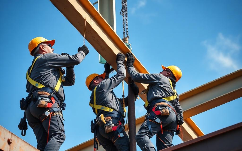
Erection safety: OSHA Subpart R fall protection and stable temporary bracing.Design review: documenting assumptions before the drawings are sealed.
ABET / licensure link. These points map to ABET Student Outcomes 2 and 4 — engineering design within realistic constraints, and recognition of ethical and professional responsibilities. Expect NCEES FE and PE exam questions on the NSPE Code of Ethics, OSHA construction requirements, and the engineer's standard of care.
07
Cost analysis
Web reinforcement economics
Approach
•Rolled beams rarely need stiffeners; adding them is usually more expensive than a thicker web or heavier section.
•Each pair of fitted stiffeners is a cut, fit, and weld operation — price it as shop labor, not steel.
•Coping and reinforcing a coped web at high shear can cost more than the beam itself.
Worked cost example — Stiffeners vs heavier beam at a high-shear support
Basis: Vu = 210 kip
Line item
Qty
Rate
Cost
Option A — add bearing stiffener pair
2 pairs
$320
$640
Option B — upsize beam, +8 lb/ft × 32 ft
0.128 ton installed
$2,700
$346
Shop welding + inspection (Option A)
3 hr
$95
$285
Estimated total
$1,271
Takeaway. The heavier beam (≈$346) undercuts the stiffener detail (≈$925) — avoid shop labor whenever steel can do the job.
Unit rates are representative US averages for teaching purposes. On a real project, price with current local rates (RSMeans, fabricator quotes, or contractor pricing) and state the estimate date.
08
Animated concepts
Key mechanics visualised — watch the strain profile, stress block, or buckled shape evolve
Web shear buckling & tension field
Slender webs buckle diagonally before yielding; a post-buckling tension field (G3) recovers strength between stiffeners.
09
Engineering figures
Full-page reference diagrams — the visual vocabulary you will use for the rest of the course
§7.6.1
Girder in service
Fig. 7.1Steel plate girder with stiffeners
Deep plate girder — the web is doing all the shear work.
§7.6.2
Web buckling
Fig. 7.2Diagonal wrinkle in a slender web
Slender-web shear buckling — Cv1 < 1.0, then post-buckling tension-field if stiffeners exist.
§7.6.3
Intermediate stiffeners
Fig. 7.3Bolted transverse stiffener
Transverse stiffeners divide the web into shear panels of aspect ratio a/h.
§7.6.4
Web crippling
Fig. 7.4Web crippled under bearing
Local web failure at a short-bearing reaction — the J10 check.
10
Worked examples
Full textbook solutions — problem, theory, step-by-step, verification, interpretation
Example 7.1
W18x50 shear check — phi_v*Vn per G2.1
The W18x50 (A992) filler beam of Ex. 6.1 has factored end reaction Vu = 90 kips. Verify web shear per AISC 360-22 G2.1 and cross-check with Manual Table 3-2.
Problem statement
A W18x50 (A992) beam has end reaction Vu = 90 kips. Verify phiv*Vn per AISC 360-22 G2.1 and confirm with Manual Table 3-2.
FIG. 7.1 — Web shear is the entire story of Chapter G.DIMW18x50 web carries the shear — Aw = d·tw, Vn = 0.6·Fy·Aw·Cv1.
Given
W18x50: d = 18.0 in, tw = 0.355 in, h/tw = 45.2
A992 steel: Fy = 50 ksi, E = 29,000 ksi
Vu = 90 kips (factored)
Find
phiv*Vn per G2.1
Utilisation Vu/phiv*Vn
Assumptions
Rolled I-shape (not built-up girder)
Bearing details verified separately (J10)
Code references
AISC 360-22 G2.1(a) — phiv pocket
AISC 360-22 G2.1(b) — Aw definition
AISC Manual Table 3-2
Theory & approach
For rolled I-shapes with h/tw <= 2.24*sqrt(E/Fy), Cv1 = 1.00 and phiv = 1.00. Vn = 0.60*Fy*Aw*Cv1.
The pocket check, Aw definition, and product all reconcile with Manual Table 3-2 exactly.
Final answer
phiv*Vn = 192 kips; utilisation = 47%. Beam is comfortable in shear.
Design interpretation
For most rolled W-shapes under gravity loading, shear utilisation runs 20-50%. Shear controls only for very short spans or heavy point loads.
Common mistakes
Using Aw = (d − 2tf)*tw — that under-counts the web area.
Using phiv = 0.90 when h/tw is in the phiv = 1.00 pocket.
Forgetting to run J10 at the reaction — G2.1 alone is not enough for bearing.
Engineering insight
The 2.24*sqrt(E/Fy) = 53.9 threshold covers 90%+ of rolled W-shapes. If h/tw > 53.9 you likely have a plate girder or a slender custom web.
References
· AISC 360-22 Chapter G
· AISC 360-22 J10
· AISC Manual 16th ed., Table 3-2
11
Guided practice
Compute the governing variables — hints unlock as you need them
A W14×22 (A992) has d = 13.7 in, t_w = 0.230 in, h/t_w = 53.3. Compute the design shear strength φ_v·V_n per AISC 360 §G2.1, state whether C_v1 = 1.0 applies, and interpret the result relative to a Vu = 60 kip end reaction.
Solve the chapter's design task — compute each governing variable
Design task
A W12×26 (A992) beam is checked for shear per AISC G2. Compute the web area Aw, verify the web slenderness so Cv1 = 1.0, and report the design shear strength φv Vn.
These questions reference AISC Steel Construction Manual (16th ed.) — sections, equations, and tables are cited explicitly. Use a calculator. Each question offers a clue you may reveal before answering. Submissions are recorded to your account once signed in.
C7-01AISC 360-22 §G2.1
1. W18×50 (d = 18.0, tw = 0.355). Compute the shear area Aw used in §G2.
C7-02AISC 360-22 §G2.1(a)
2. Same beam. Check web slenderness against 2.24·√(E/Fy) for A992. h = 15.82 in, tw = 0.355.
C7-03AISC 360-22 Eq. G2-1
3. With Case (a) satisfied (φv = 1.00, Cv1 = 1.0), compute φv·Vn.
C7-04Statics
4. Same beam under wu = 2.0 k/ft over L = 30 ft (simple). Compute the support shear Vu and DCR.
C7-05AISC 360-22 §G
5. Now increase demand to wu = 8.0 k/ft (same span). New Vu and does W18×50 still pass shear?
C7-06AISC 360-22 §G2.1(b)
6. For Case (b) (h/tw > 2.24√(E/Fy)) with a rolled W, per §G2.1(b) the coefficients used are:
C7-07AISC 360-22 §G2.2(b)
7. Transverse stiffeners for tension-field action (TFA): where are they PROHIBITED?
C7-08AISC 360-22 §G4
8. Rectangular HSS shear is checked using:
C7-09AISC 360-22 Eq. J10-2
9. Web local yielding under a concentrated load applied AT THE INTERIOR of a beam (5·k + lb rule):
C7-10AISC Manual Table 3-2
10. AISC Manual Table 3-2 lists φvVn for W18×50 as (verify against Q C7-03):
C7-11AISC 360-22 Eq. G2-3, G2-6
11. When h/tw exceeds 2.24√(E/Fy) but is below the slender-web threshold, Cv1 in Eq. G2-3 depends on:
C7-12AISC 360-22 §G
12. A composite floor beam (top flange continuously braced by the slab) — does shear still need to be checked?
C7-13Statics
13. On the same 30-ft beam, if a 20-k point load is applied at 3 ft from the support (in addition to wu = 2.0 k/ft), recompute the max Vu.
Attach your handwritten or typed step-by-step solution for this chapter's graded quiz. The instructor can download every submission. PDF only, up to 25 MB.
How your upload will be graded
Your file — PDF, Word document, scanned handwriting or a photo — is read page by page like an experienced structural engineering instructor would. The scan is validated first, then your reasoning, structural model, calculations, diagrams, code basis and final answers are graded on process, not just the final number. Design work is additionally reviewed against AISC 360-22 and ACI 318-19. Partial credit applies, and one early mistake carried correctly forward is only penalized once.
Before you attach the file
Include every page, in order and right way up — a missing page cannot earn credit.
Keep margins in frame: nothing cropped at the edges, especially boxed final answers.
Scan or photograph in good, even light — no shadows, glare or blur; 300 dpi or a steady phone scan.
Write in dark pen; faint pencil is the most common 'UNREADABLE — INSTRUCTOR REVIEW REQUIRED' flag.
Include all diagrams, FBDs, shear/moment diagrams and section sketches — label them.
Number each question the same way the assignment does, and note anything you skipped.
Show units on every line and box your final answers.
Combine everything into ONE file (PDF preferred; Word, JPG or PNG accepted) under 20 MB.
Sign in to upload your worked solution.
16
FE exam preparation
NCEES-style practice with timer, equation sheet, and mastery tracking
 Objective 01