Introduction to Structural Steel Design
Overview of steel as a structural material, the design process, and code framework.
- AISC 360-22 — Specification for Structural Steel Buildings
- AISC Manual 16th Ed. — Design tables and worked examples (18 parts)
- ASCE 7 — Minimum Design Loads — load combinations and live-load reduction
- ACI 318-19 — Reference: Concrete code for context (LRFD/ASD comparison only)
Lecture Notes
Lecture Notes: Chapter 1 — Fundamental Concepts of Structural Design
1. Introduction to Structures & The Design Process
A STRUCTURE is a system of connected components designed to support applied forces while executing its primary architectural or engineering function. This course focuses strictly on civil structures (e.g., commercial buildings, bridges, communication towers) rather than military or mechanical variants (e.g., naval hulls, aircraft bulkheads, or tanks).
Structural engineering balances both technical analysis and design innovation. Every project is executed with strict adherence to five baseline criteria:
- Safety: Preventing structural collapse under extreme loading distributions.
- Serviceability: Eliminating disruptive real-world behaviors (e.g., excessive vibrations or deflections) during routine operation.
- Aesthetics: Harmonizing visually with local surroundings and architectural goals.
- Economy: Minimizing structural material cost, manufacturing labor, and lifecycle expenses.
- Environmental Conditions: Resisting specialized regional factors like seismic acceleration, wind shear currents, or snow loads.
The Structural Engineering Workflow Loop
- Establish structural configuration and geometric layout options.
- Identify applicable design regulations and calculate anticipated structural loads (ASCE 7).
- Perform structural frame analysis to resolve internal element design actions (bending moments, axial forces, shear).
- Size physical elements and engineer safe connection detailing matching limit-state rules.
- Evaluate structural alternatives and execute design optimization loops.
2. Four Basic Structural Types
A structural SYSTEM is composed of individual structural MEMBERS joined by structural CONNECTIONS. Modern industrial layouts integrate variations of these four primary frameworks.
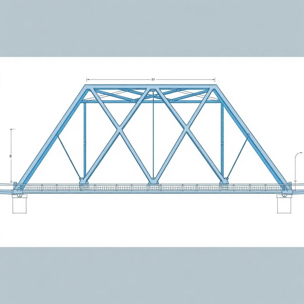
A. Trusses
Formed by arranging slender elements in triangular geometries. Because members are assumed to be pin-connected at joints, they develop primarily axial tension or compression forces without localized bending moments. Classified as planar trusses (roof trusses, traditional bridges) or space trusses (transmission towers).
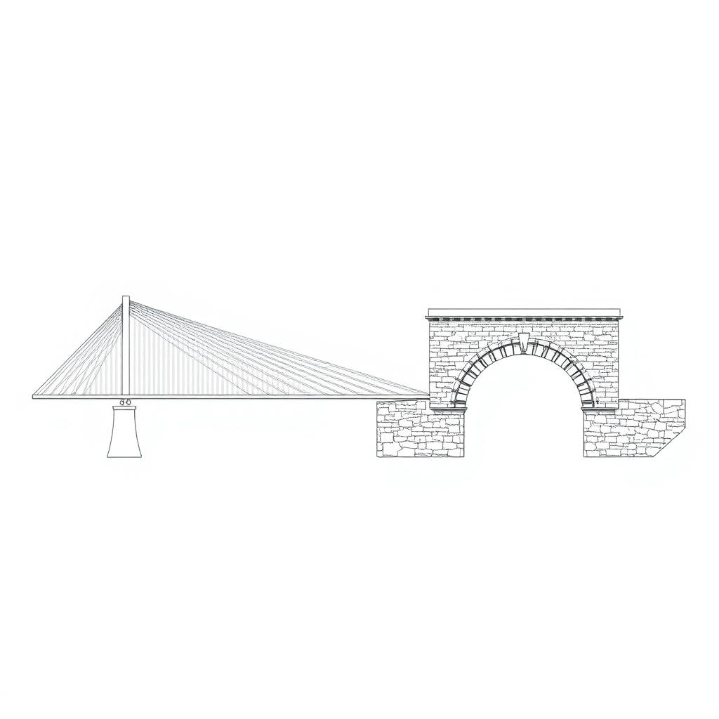
B. Cables & Arches
Optimized systems targeting specific internal force profiles for long-span bridges or overhead sports-dome roofs. Flexible cables carry load entirely in tension (relying on geometric sag), whereas rigid arches support forces primarily in compression.
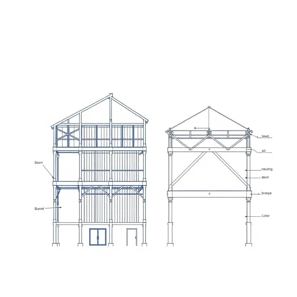
C. Frames
Composed of interlocking beams and columns. Standard configurations divide into braced frames (which integrate diagonal pin-connected steel angles to handle side-sway forces) and rigid moment frames (which incorporate continuous, stiff monolithic joints to resist moment rotations without bracing elements).
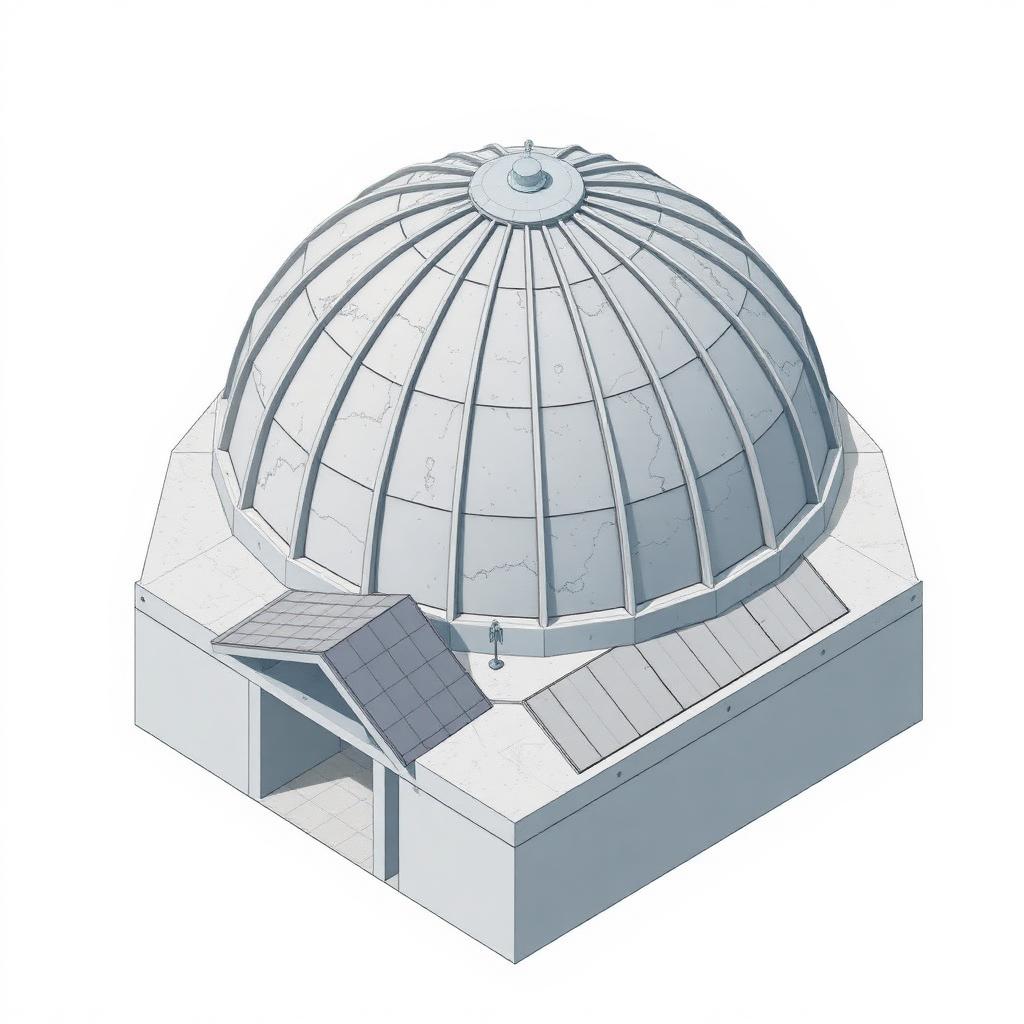
D. Surface Structures
Composed of thin, curved or folded continuous elements (membranes, thin plates, or concrete shells). Forces resolve into highly efficient in-plane tensile or compressive fields rather than heavy bending moments. Examples include concrete domes, aircraft hangars, and folded-plate roofs.
3. Structural Members
Individual members are classified by the dominant internal force they resist:
- Tension members (ties): Slender rods, angles, or cables that resist pulling forces along their axis.
- Compression members (columns / struts): Vertical or inclined members that resist axial pushing; governed by buckling stability.
- Beams: Horizontal members that resist transverse loads through bending and shear.
- Beam-columns: Members subjected to combined axial force and bending moment (the typical perimeter column of a moment frame).
- Connections: Bolted or welded details that transfer forces between members; classified as simple (shear-only), partially restrained, or fully restrained (moment).
4. Types of Loads (ASCE 7)
Gravity Loads
- Dead Load (D): Self-weight of permanent construction — slabs, beams, cladding, MEP.
- Live Load (L): Movable occupancy loads — people, furniture, storage. Tabulated by occupancy in ASCE 7 Table 4.3-1.
- Roof Live (Lr) & Snow (S): Maintenance access vs accumulated snow per regional ground-snow maps.
- Rain (R): Ponding load when drainage is impaired.
Lateral & Environmental Loads
- Wind (W): Velocity pressure converted to surface pressure using exposure, topography, and gust factors (ASCE 7 Ch. 26–30).
- Seismic (E): Inertial forces from ground acceleration; determined by site class, SDS / SD1, and a response-modification factor R (ASCE 7 Ch. 12).
- Thermal, settlement, and impact loads: Special-case actions handled per ASCE 7 §2.3.
⚠ Critical Reminder
Never design a member for a single load case in isolation. The governing demand always comes from an LRFD load combination (e.g., 1.2D + 1.6L, 1.2D + 1.0W + L + 0.5Lr) — covered in Chapter 2.
5. Looking Ahead
The remainder of this course applies these foundations to steel design: load combinations and LRFD (Ch. 2), material behavior (Ch. 3), tension members (Ch. 4), compression and beams (Ch. 5–6), connections (Ch. 7–9), and a capstone building design.
6. Regulatory Codes & Design Frameworks
To ensure structural performance and protect public safety, building design in the United States follows specialized codified standards:
- Structural Steel: Governed by AISC 360-22 (Specification for Structural Steel Buildings) and detailed in the 16th Edition of the AISC Steel Construction Manual (split into 18 primary parts).
- Reinforced Concrete: Controlled by ACI 318-19 (Building Code Requirements for Structural Concrete).
- Design Loading: Derived from ASCE 7 (Minimum Design Loads and Associated Criteria for Buildings and Other Structures), establishing regulatory live, dead, seismic, wind, and environmental limits.
7. LRFD vs. ASD: Design Philosophy & Numerical Metrics
The AISC code provides structural engineers two distinct methods side-by-side. Both target structural safety but distribute safety factors differently:
Load and Resistance Factor Design (LRFD)
A modern limit-states standard. It accounts for load variation by scaling service demands up using overload factors (γi > 1.0) and scales nominal capacities down using a resistance factor (φ < 1.0) based on material limit states.
Allowable Strength Design (ASD)
A classical elastic design baseline. Unfactored service working loads (Ra) are combined directly. Overall structural margin is maintained by dividing raw nominal resistance capacity by a global factor of safety (Ω > 1.0).
8. Historical Context & Engineering Ethics Lessons
Structural engineering failure analysis reinforces that connection design and peer review are as critical to public safety as member sizing. Two major structural connection failures underscore this reality:
- Hyatt Regency Walkway Collapse (Kansas City — July 17, 1981): 114 fatalities and over 200 injuries. The disaster stemmed from a field modification that doubled the load on a critical hanger rod connection. The revised setup transferred load through a support beam box girder flange that lacked the capacity to support it, leading to a progressive punching shear failure.
- FIU Pedestrian Bridge Collapse (Miami — 2018): Critical design errors in a concrete truss connection region, coupled with insufficient peer review and a failure to halt construction when severe structural cracking appeared.
Core Lesson
Structural connections transfer forces through complex load paths. Every connection detail must undergo thorough calculation, independent verification, and rigorous peer review before field implementation.
Every chapter's worked example is one step in the design of the same building: Plan: 4 bays N–S × 3 bays E–W, each 30 ft × 30 ft. Stories: 4 @ 13 ft (52 ft roof). Composite floor: 4.5 in NW concrete on 3 VLI20 deck. Roof: 1.5 in B-deck + insulation + membrane. Materials: Wide-flange members A992 (Fy = 50 ksi, Fu = 65 ksi). Plates A572 Gr. 50. HSS bracing A500 Gr. C. Bolts A325-N 7/8 in dia. Welds E70XX. Concrete f'c = 4 ksi. Anchor rods F1554 Gr. 36.
Formula Sheet
| Name | Equation | AISC Ref |
|---|---|---|
| Design strength | φ Rn ≥ Ru | AISC 360-22 B3.1 |
Worked Example
Worked Example 1.1 — Load Identification & Member Type
Problem Statement
A typical interior column in a 4-story steel office building supports the tributary area of one bay (5 m × 6 m) at every floor. Given the loads below, classify the column, identify which loads act, and compute the factored axial demand at the first-story column using the governing LRFD combination.
Given: Dead load D = 4.0 kPa, Live load L = 2.4 kPa, Roof live Lr = 1.0 kPa, Snow S = 1.5 kPa. Tributary area per floor A = 30 m². Four floors + roof.
Step 1 — Member Classification
The element is vertical, gravity-loaded, and free of transverse load between floors → it is a compression member (column). Buckling stability will govern its design (Chapter 5).
Step 2 — Tributary Loads per Floor
Step 3 — Accumulate over 4 Floors + Roof
First-story column carries 4 floors of D & L plus 1 roof of D + (Lr or S):
Step 4 — Apply LRFD Load Combinations (ASCE 7 §2.3)
Reference — Mild-Steel Stress–Strain Behavior
The material curve below sets the stage for every limit state we will use: yielding is bounded by Fᵢ, ultimate capacity by Fᵘ, and ductility by the plateau and strain-hardening regions before rupture.
FE-Style Worked Examples (6)
Each example mirrors the NCEES FE Civil Reference Handbook style: brief givens, a labeled figure, AISC section reference, step-by-step numeric solution, and a single boxed answer.
- Combo 11.4D = 1.4(20) = 28 k
- Combo 21.2D + 1.6L + 0.5S = 24 + 80 + 5 = 109 k
- Combo 31.2D + 1.6S + 0.5L = 24 + 16 + 25 = 65 k
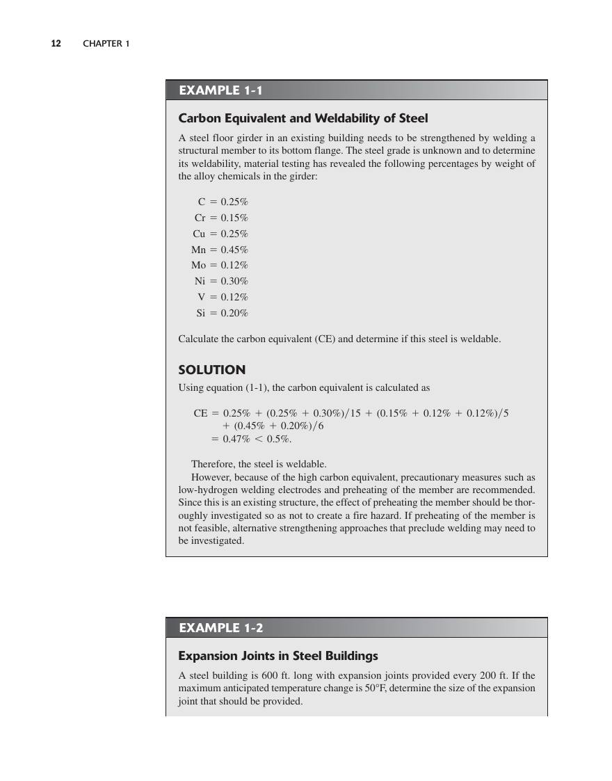
Textbook — Aghayere & Vigil (2009)(2 worked examples with figures + numerical answers)
Worked examples scanned directly from the CEGR 436 course textbook. Each card shows the original page (figure + full step-by-step solution) and adds an FE-style numerical multiple-choice prompt with answer key.
Chapter 1 of the textbook introduces steel as a building material, the AISC Manual organization, and the structural-steel design / construction process. Students are introduced to the kinds of structural members (tension, compression, flexure, beam–column, surface) and the rules of thumb for laying out floor and roof framing.
- Properties of structural steel: Fy, Fu, E = 29,000 ksi, elongation, and the importance of ductility.
- Common shape families: W, M, S, HP, C, MC, L (angles), HSS (rectangular/round), pipes, plates, bars.
- ASTM grades: A992 (W-shapes), A36 (M/S/C/L/plates), A500 Gr.B/C (HSS), A53 (pipe), A572 (high-strength plates).
- Framing layout rule of thumb: beam spacing 6–12 ft, beam span / depth ≈ 20–24, girder span / depth ≈ 15–20.
- Steel design + construction process: schematic → DD → CD → shop drawings → erection → punch list.
FE Practice Bank (3)
Multiple-choice problems pulled from the instructor's CEGR 492 FE Review packet (EasyFEExam © 2025, Steve Efe, PhD). Pick an answer, then click Reveal solution.
Practice Problems
- [E] List the four basic structural types with one steel example each (truss, cable/arch, frame, surface).
- [E] Identify the five basic structural members and the steel cross-section family typically used for each.
- [E] Define safety, serviceability, aesthetics, economy, and environment in one sentence each.
- [E] Name the U.S. governing documents for steel (AISC 360-22, AISC Manual 16th Ed.) and loads (ASCE 7-22).
- [E] State the LRFD and ASD design inequalities and identify each symbol.
- [M] For a 30 ft x 30 ft typical bay with W-beams at 10 ft o.c., sketch the gravity load path from a 100 psf live load to the spread footing.
- [M] Classify each member as TENSION, COMPRESSION, FLEXURAL, or BEAM-COLUMN: hanger rod; interior column of a moment frame; floor beam; X-brace diagonal; corner column of an unbraced frame.
- [M] For A992 W-shape Fy = 50 ksi, compute εy = Fy/E and compare to εcu = 0.003 of concrete.
- [M] A simply supported beam carries wD = 0.80 k/ft and wL = 1.20 k/ft on a 28 ft span. Show numerically why LRFD and ASD do NOT give the same factor of safety.
- [M] A 4-story office building, 5 x 4 bays at 30 x 28 ft. Estimate gravity demand on an interior base column for DL = 90 psf, LL = 50 psf (use live-load reduction).
- [H] Case study (1 paragraph) of the Hyatt Regency walkway collapse (1981). Identify the connection-detail failure mode and tie it to one AISC 360-22 chapter.
- [H] Compare braced-frame vs moment-frame lateral systems on drift, connection cost, architectural flexibility, and seismic ductility.
- [H] For a 6-story unbraced moment frame H = 78 ft and wind drift limit H/400, compute the maximum allowable roof drift.
- [H] Read AISC 360-22 §B3 and summarize LRFD vs ASD load-combination logic in three bullets each.
- [H] Design-philosophy essay (≤300 words): why is connection design and peer review as critical as member design? Use FIU 2018 collapse as case.
- Trace one load increment from slab → beam → girder → column → footing and label each member type as you go.
- When asked LRFD vs ASD, separate FACTORED load (Σγi·Qi) from RESISTANCE (φRn or Rn/Ω).
- Live-load reduction applies only to KLL·AT > 400 ft² (ASCE 7 §4.7).
- AISC 360-22 §A1, B3
- AISC Manual 16th Ed., Part 2
- ASCE 7-22 §2.3, §4.7
Quiz (3 FE-bank + 2 concept)
Common Student Mistakes
- Mixing ASD and LRFD load combinations in the same problem.
- Using nominal strength Rn instead of design strength φRn.
- Forgetting to check every limit state listed in the AISC chapter.
"Professor Explains" Script
Today we're talking about introduction to structural steel design. Think of this topic as one step in the LRFD workflow: identify the demand, identify the limit states from the relevant AISC chapter, then check that φ·Rn is at least equal to Ru. We'll walk through the failure modes, the equations, and a worked example. Pay close attention to where the resistance factor changes — that's where students lose points on exams.