20

Capstone Design Project

Why Structural Steel?

Design a small steel-framed building bay end-to-end.

240 minAdvanced3 objectives
§01Section 01

Engineering story

Engineering story
Chapter 20 · Capstone Design Project

Design a small steel-framed building bay end-to-end.

A real project narrative for this chapter will be authored as this chapter migrates to the v3.0 structured schema.

§02Section 02

Learning objectives

After this chapter you will be able to
  • Design a full steel bay end-to-end
  • Coordinate gravity + lateral systems
  • Produce a construction submittal
§03Section 03

Engineering motivation

§04Section 04

Failure mechanisms

Failure mechanisms & lessons learned

Photographs and lessons-learned case studies for this topic will be added during chapter migration.

AISC Reference Box
  • AISC 360-22Specification chapter governing this topic
  • AISC Manual 16th Ed.Design tables and worked examples

Why This Chapter Matters

The capstone integrates every earlier chapter into one deliverable: a code-compliant, buildable, economical steel building. It is the closest classroom simulation of professional structural engineering practice — and the assignment most cited by hiring managers.

Learning Objectives

  • Develop a full gravity + lateral load path from ASCE 7 loads to foundations.
  • Design all typical members: tension, compression, flexure, shear, combined, and connections.
  • Produce structural drawings: framing plan, elevation, typical details, base-plate schedule.
  • Compile a submittal-quality calculation package with AISC references.
  • Present the design to a panel and defend every governing check.

Where This Chapter Is Used

This chapter closes the course. It is graded across a 16-week rubric that mirrors real engineering deliverables and prepares students for the FE exam and entry-level structural roles.

Chief Structural Engineer's Briefing
"Good morning, team. The architect just handed us the final floor layout for the Cardinal Square Office Building — four stories, 3 × 4 bays at 30 ft, composite floor on metal deck, and concentrically-braced frames on the perimeter. Over the next sixteen weeks you own this structure end-to-end: framing plan, load takeoff, every beam, every column, every brace, every connection, every base plate, and the second-order stability check that ties it all together. A mistake at any stage compromises occupant safety, drives up steel tonnage, or forces a costly redesign during shop-drawing review. Your task is to deliver a defensible AISC 360-22 / ASCE 7-22 LRFD design package that a reviewer can follow without asking a single question. Let's build it."
1 · Real Engineering Scenario

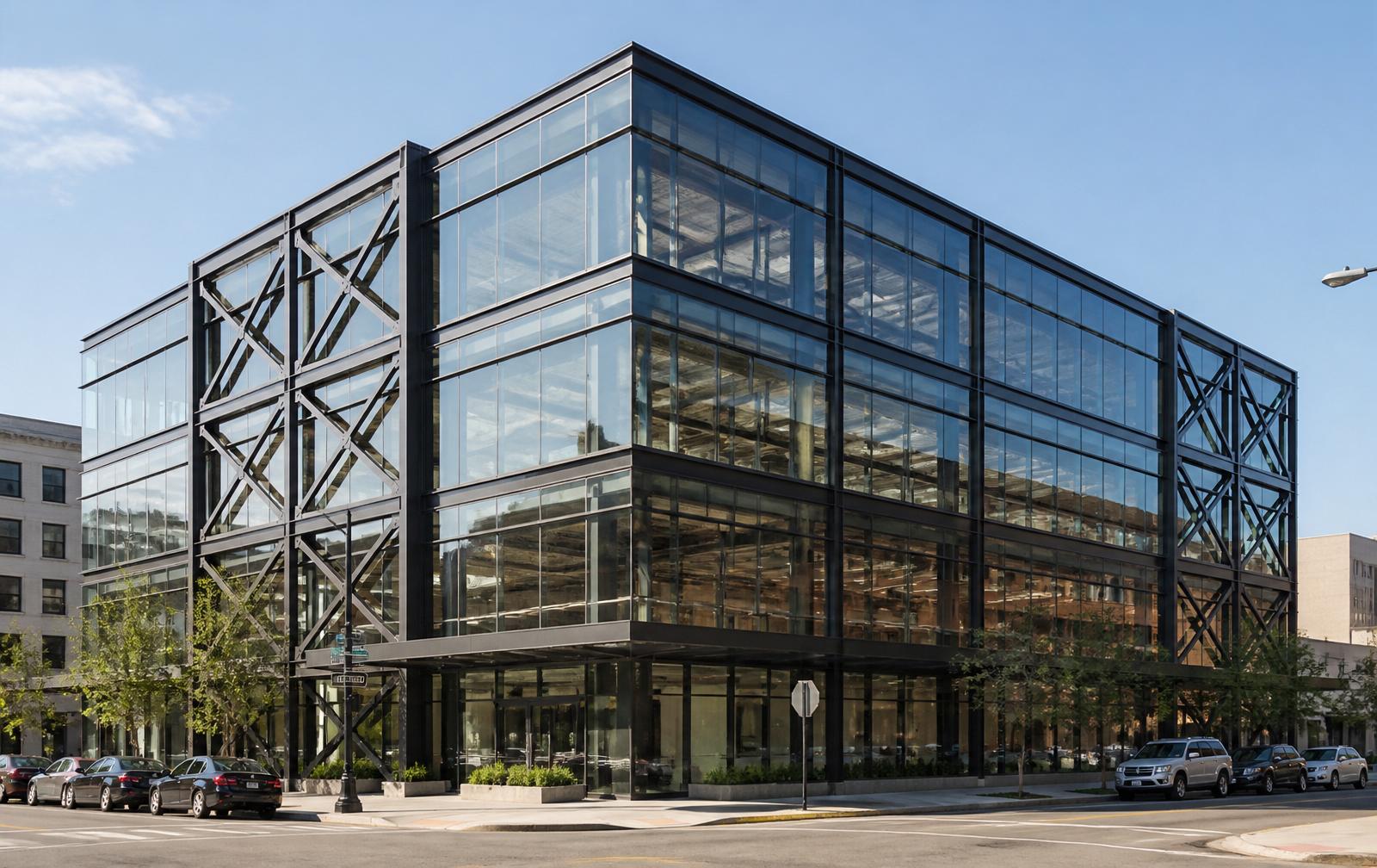
Rendering of the Cardinal Square 4-story steel-framed office building with perimeter braced frames
Cardinal Square — 4-story steel-framed office, 90 ft × 120 ft footprint, perimeter concentrically-braced frames visible in the end bays.

You are the structural EOR for Cardinal Square, a new four-story speculative office building on an infill lot in a mid-Atlantic city. The developer wants efficient bays (30 ft × 30 ft) to allow flexible tenant fit-out, a floor-to- floor height of 13 ft to accommodate raised access flooring and generous ceilings, and a Class-A finish schedule that leaves no room for cracked partitions or bouncy floors. The site is Exposure B with a 110 mph design wind, and the seismic hazard is moderate (SDS ≈ 0.30 g).

The architectural program is fixed: 90 ft × 120 ft footprint, open-plan tenant spaces, and no interior shear walls. That means the lateral system must live in the perimeter — concentrically-braced frames (CBF) in the two end bays each direction — and the interior is gravity-only with simple shear-tab connections. Steel arrives on-site in eight weeks. Every decision you defer costs money in RFIs and shop-drawing changes.

What could go wrong? Under-sized braces buckle under wind reversal. Over-sized columns waste tonnage. A missed block-shear check at a gusset can initiate progressive collapse of the entire lateral system. A miscalculated deflection cracks partitions on day one. You are here to prevent every one of those outcomes.
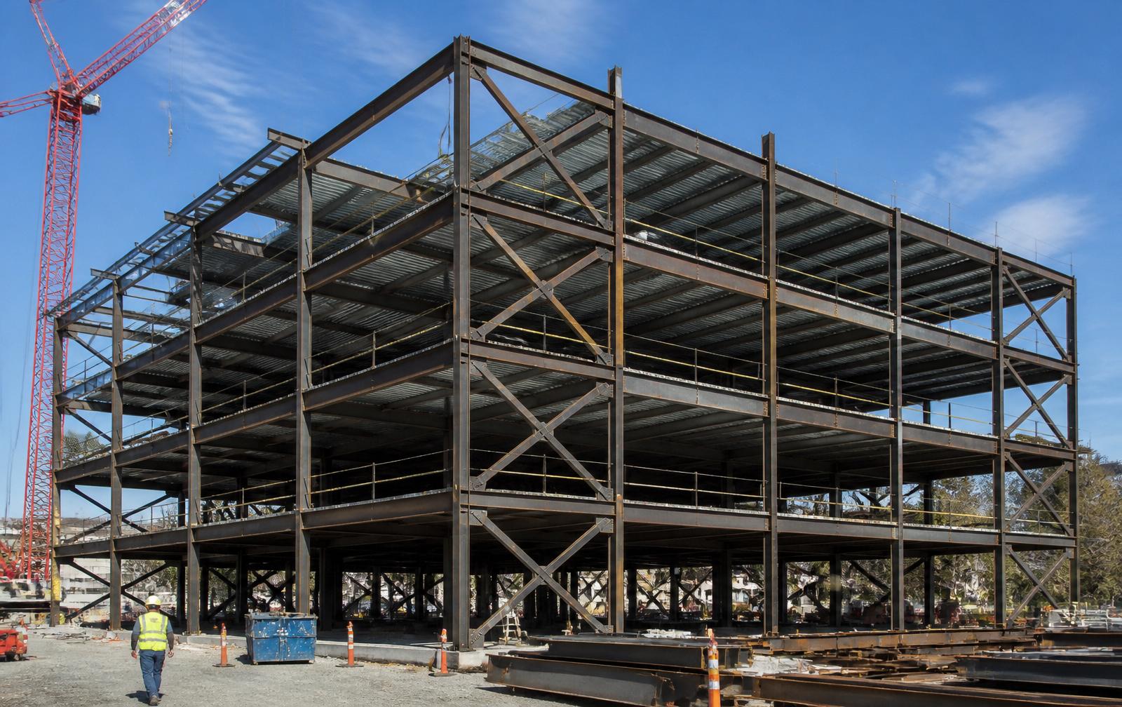
Erected structural steel frame with X-bracing on perimeter bays during construction
Reference photo — a comparable erected steel frame showing perimeter X-bracing, wide-flange columns and beams, and composite metal deck. Your Cardinal Square design must produce a set of drawings that a fabricator can build like this.

2 · Why This Capstone Matters

  • Integration. Chapters 1–19 taught you one limit state at a time. Real design forces you to coordinate all of them on the same geometry.
  • Safety. Every member you size and every connection you detail is the last line of defense for the occupants of this building.
  • Economy. Steel tonnage drives cost. A well-tuned design can save 10–20% of the frame weight versus a conservative rule-of-thumb layout.
  • Serviceability. Deflection and vibration control the tenant experience — cracked drywall and bouncy floors get you fired.
  • Code compliance. AISC 360-22 and ASCE 7-22 are the law. Every check must cite the exact section that authorizes it.
  • Professional practice. The signed calc binder you produce is the deliverable your future employer expects on day one.

3 · Engineering Failure Case Study — Hartford Civic Center (1978)

Collapsed steel space-frame roof under snow load at night
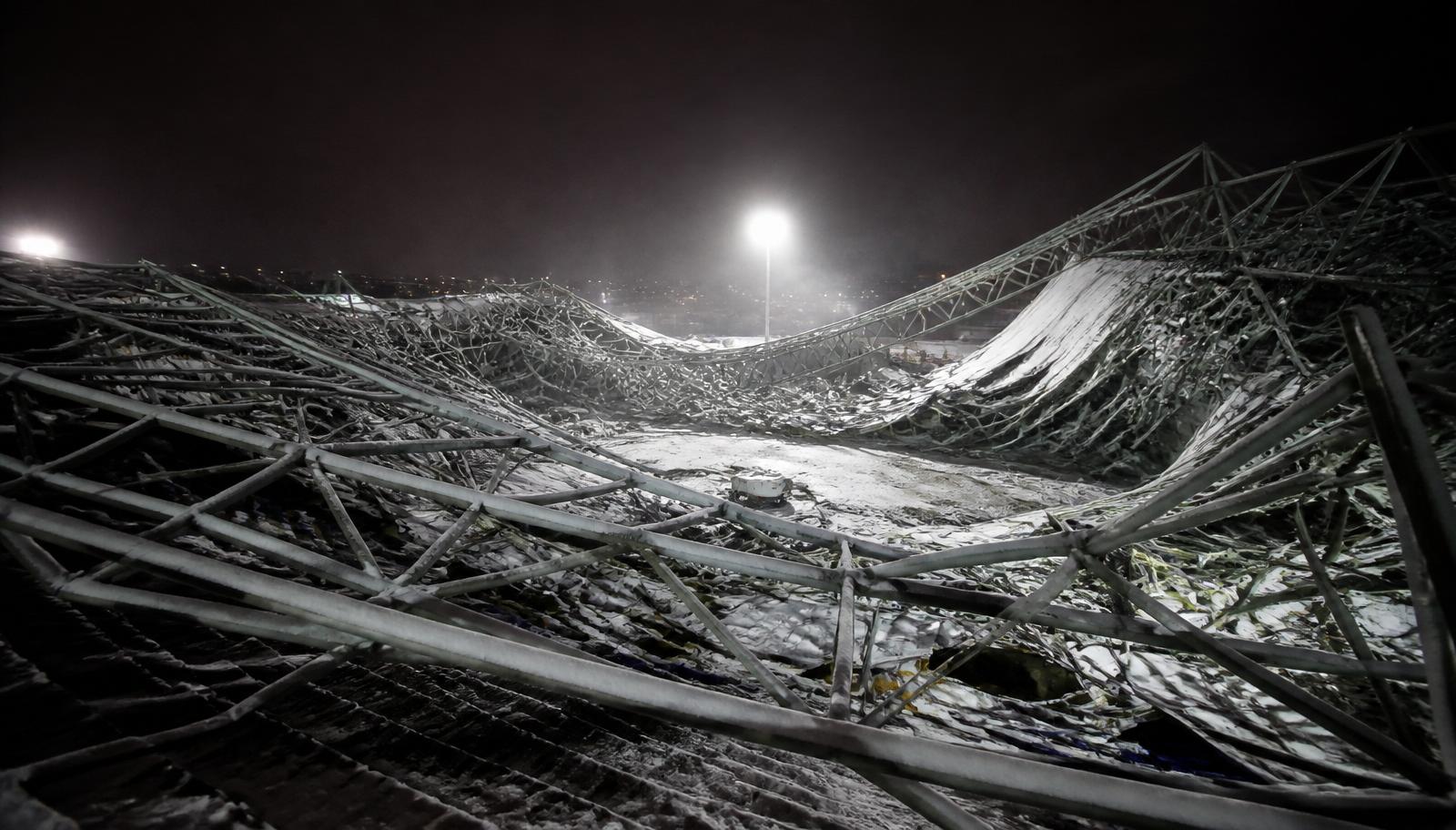
Hartford Civic Center Coliseum roof — collapsed under snow load, January 18, 1978. Illustration of the type of large-span space-frame failure that drives the AISC stability provisions you will apply in Chapter 17.

On the night of January 18, 1978, the 300-ft × 360-ft steel space-frame roof of the Hartford Civic Center Coliseum collapsed under snow load — six hours after 5,000 fans had left a basketball game. The frame had been in service for four years. No one died only because the timing was accidental.

Root cause. A cascade of independent errors: (a) top-chord compression members were sized assuming lateral bracing that construction never provided; (b) the computer model idealized joints as pinned when they behaved as partially fixed, changing effective lengths; (c) design snow load was underestimated; (d) field observations of visible deflection during construction were dismissed. Each error alone was survivable — together they were catastrophic.

Lessons for Cardinal Square. This capstone forces you to explicitly declare every assumption (K-values, unbraced lengths, joint fixity, load magnitudes) and to have your Checker independently verify each one. You will apply the Direct Analysis Method (Ch. 17) precisely so that the analysis model matches the constructed reality.

4 · Where the Capstone Fits in the Design Process

Design Process Pipeline
1. Architect delivers program & geometry2. Structural Engineer (YOU) — system selection & load path3. Load determination per ASCE 7-224. Material selection (A992, A572, A500, A325, E70XX)5. Member design — tension / compression / flexure / shear / combined6. Connections — bolted, welded, shear tab, moment, base plate7. Stability check — Direct Analysis Method (Ch. 17)8. Serviceability — deflection, drift, vibration9. Detailing → Fabrication → Erection → Inspection → Occupancy

5 · Learning Objectives

After completing this capstone, students will be able to:
  • Explain the load path from cladding and roof deck through beams, girders, columns, and braces down to the base-plate / anchor-rod interface.
  • Identify the governing limit state for any primary member in the Cardinal Square frame and cite the exact AISC 360-22 section that controls it.
  • Analyze the structure using the Direct Analysis Method with B1/B2 amplification and reduced stiffness (τb).
  • Compute LRFD required strengths for every controlling ASCE 7-22 load combination at floor, roof, and lateral-frame locations.
  • Design beams, columns, braces, and every connection type consistent with member demands and detailing constraints.
  • Verify serviceability (L/360 live, L/240 total, drift H/400).
  • Interpret AISC Manual tables (3-2, 4-1, 4-14, 7-1, 10-1) as a practicing engineer, not a plug-and-chug student.

6 · Failure Mechanisms You Must Prevent

Gross-section yielding
Example on Cardinal Square: Tension chord of CBF brace under wind reversal.
Net-section rupture
Example on Cardinal Square: Bolted brace-to-gusset connection.
Block shear
Example on Cardinal Square: Gusset plate tear-out at brace end.
Flexural yielding (M_p)
Example on Cardinal Square: Composite floor girders under 1.2D+1.6L.
Lateral-torsional buckling
Example on Cardinal Square: Roof girders with widely-spaced kickers.
Web local yielding / crippling
Example on Cardinal Square: Beam-to-column shear tabs at heavy end reactions.
Flexural buckling of columns
Example on Cardinal Square: Interior gravity columns, KL/r governed.
Combined P-M interaction
Example on Cardinal Square: Perimeter columns of the braced-frame line.
Bolt shear / bearing
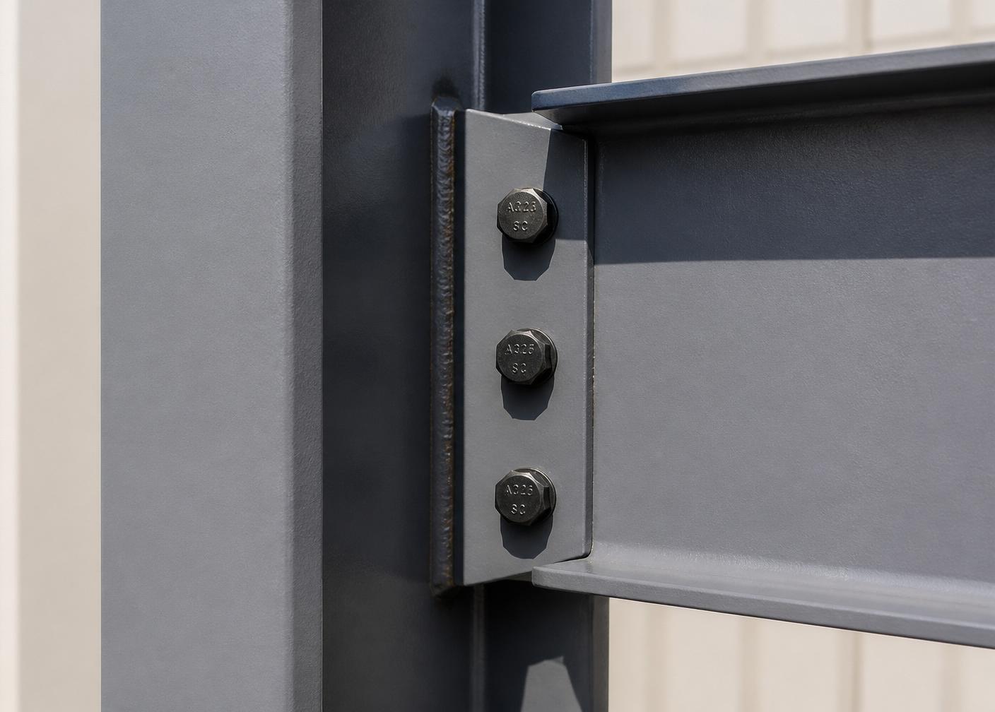
Example on Cardinal Square: A325-N bolts in all shear tabs and gussets.
Weld strength / rupture
Example on Cardinal Square: E70XX fillets on shear tabs and gusset welds.
Concrete bearing / anchor pull-out
Example on Cardinal Square: Base-plate / anchor-rod assembly.
P-Δ instability
Example on Cardinal Square: Overall frame under 1.2D+1.0W+1.0L+0.5Lr.
Deflection / vibration
Example on Cardinal Square: Typical 30-ft filler beams under sustained live load.
Close-up of shear-tab beam-to-column connection with A325 bolts
Bolted shear-tab connection — the detail behind bolt shear, bearing, block shear, and weld-strength limit states from the mechanism list above.
Perimeter braced-frame bay under construction
Perimeter braced-frame bay — X-braces control gross-yielding, net rupture, block shear, and column P-M interaction on the lateral line.

7 · Where Capstone-Style Integrated Design Is Used

Every real project — commercial office towers, hospitals, schools, parking garages, distribution warehouses, transit stations, industrial plants, and mid-rise residential over podium — is a Cardinal Square in disguise. The same load-path logic, the same member checks, the same Manual tables, and the same LRFD combinations recur on every job you will ever stamp. The building type changes; the discipline does not.

8 · Prerequisite Knowledge Refresher

  • Statics & mechanics — equilibrium, tributary areas, moment & shear diagrams.
  • Strength of materials — normal & shear stress, section properties (I, S, Z, r).
  • Structural analysis — indeterminate frames, moment distribution / stiffness, effective length.
  • Steel properties — A992 (Fy=50, Fu=65), A572 Gr. 50, A500 Gr. C HSS, A325-N bolts, E70XX electrodes.
  • LRFD philosophy — ϕRn ≥ Ru, load factors, resistance factors, reliability index β.
  • ASCE 7-22 loads — dead, live, live-load reduction, snow, wind, seismic, load combinations.
  • AISC Manual — Part 1 shape properties, Part 3 beam tables, Part 4 column tables, Part 7 bolts, Part 8 welds, Part 10 connections.

9 · Capstone Roadmap

16-Week Capstone Pipeline
1. Real building program — Cardinal Square2. Framing plan & load-path narrative (Weeks 1–2)3. Materials + section properties (Week 3)4. Members: tension → compression → flexure → shear → combined (Weeks 4–8)5. Midterm gate (S7, Week 8)6. Connections: bolted → welded → shear-tab → moment → base plate (Weeks 9–13)7. Stability, serviceability, integrated framing (Weeks 14–15)8. Final report, drawings, and oral defense (Week 16 / Finals)

10 · Lecture Notes — Think Like the EOR

The capstone is not a new set of equations — every equation you need lives in Chapters 1–19. What is new is the decision-making. At every step you will confront a real design question that has more than one defensible answer. Your job is to pick one, document why, and be ready to defend it at the final review.

Think Like an Engineer #1

The owner wants to add a fifth floor after you finish schematic design. Which of your Week-1 assumptions (bay size, column spacing, brace configuration) survives? Which member do you re-check first, and why?

Think Like an Engineer #2

Your fabricator says A992 W-shapes are in short supply and offers to substitute A572 Gr. 50 built-up plate girders on the roof. Which limit states change? Which stay the same? What is your recommendation to the owner?

Think Like an Engineer #3

At the midterm the Checker flags that your CBF brace uses a K = 1.0 assumption but the gusset detail behaves closer to K = 0.8. What is the impact on ϕPn? Do you revise the design, or defend the conservative value? Cite AISC 360-22 Chapter C.

Before every worked submission — restate the Engineering Problem, list Known / Unknown / Sketch / Assumptions, cite the applicable AISC specification and ASCE load combo, write the formula, substitute, calculate, perform the code check, interpret the result, and finish with a one-line Engineering Decision. Every weekly submission is graded against that template.

Capstone Connection

Everything below — Project Introduction, Project Details, Weekly Roadmap, Grading Rubric, and Weekly Expectations — is the operational package that turns the lecture above into your 16-week Fall 2026 deliverable. Read the briefing, then execute.

Project Introduction — Cardinal Square

Why this project. Real structural engineering is not one isolated limit-state check — it is the coordinated design of dozens of members and connections that all share the same geometry, load path, and material choices. The Cardinal Square capstone forces you to carry a single building from framing plan to base plate over 16 weeks, using every skill from Chapters 1–19.

Objective. Deliver a complete, AISC 360-22 / ASCE 7-22 LRFD design for a 4-story steel-framed office building — including framing plans, load takeoff, member design (tension, compression, flexure, shear, combined), connections (bolted, welded, shear tab), base plates, second-order effects, composite action, and serviceability — presented as a signed calc binder + structural drawing set + oral defense.

Learning outcomes. By the end of the capstone every student can (1) trace a load from cladding to footing, (2) size any primary member for the governing LRFD limit state with the correct AISC reference, (3) design bolted and welded connections consistent with member demands, (4) apply the Direct Analysis Method with B1/B2 amplification, (5) produce a defensible calc package that a reviewer can follow without asking questions.

Student role. Groups of 3–4 act as the structural EOR team. Assigned roles: Project Engineer (coordinates load path and section selection), Checker (independent verification of every calc), Drafter (produces framing plans, elevations, and details), and Spec Lead (materials memo and AISC section citations on every check). Roles rotate at the midterm.
Project Details

  • Occupancy: Business office (ASCE 7 Risk Category II).
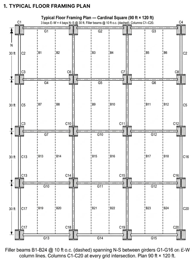
  • Plan: 3 bays E–W × 4 bays N–S @ 30 ft × 30 ft (90 ft × 120 ft footprint).
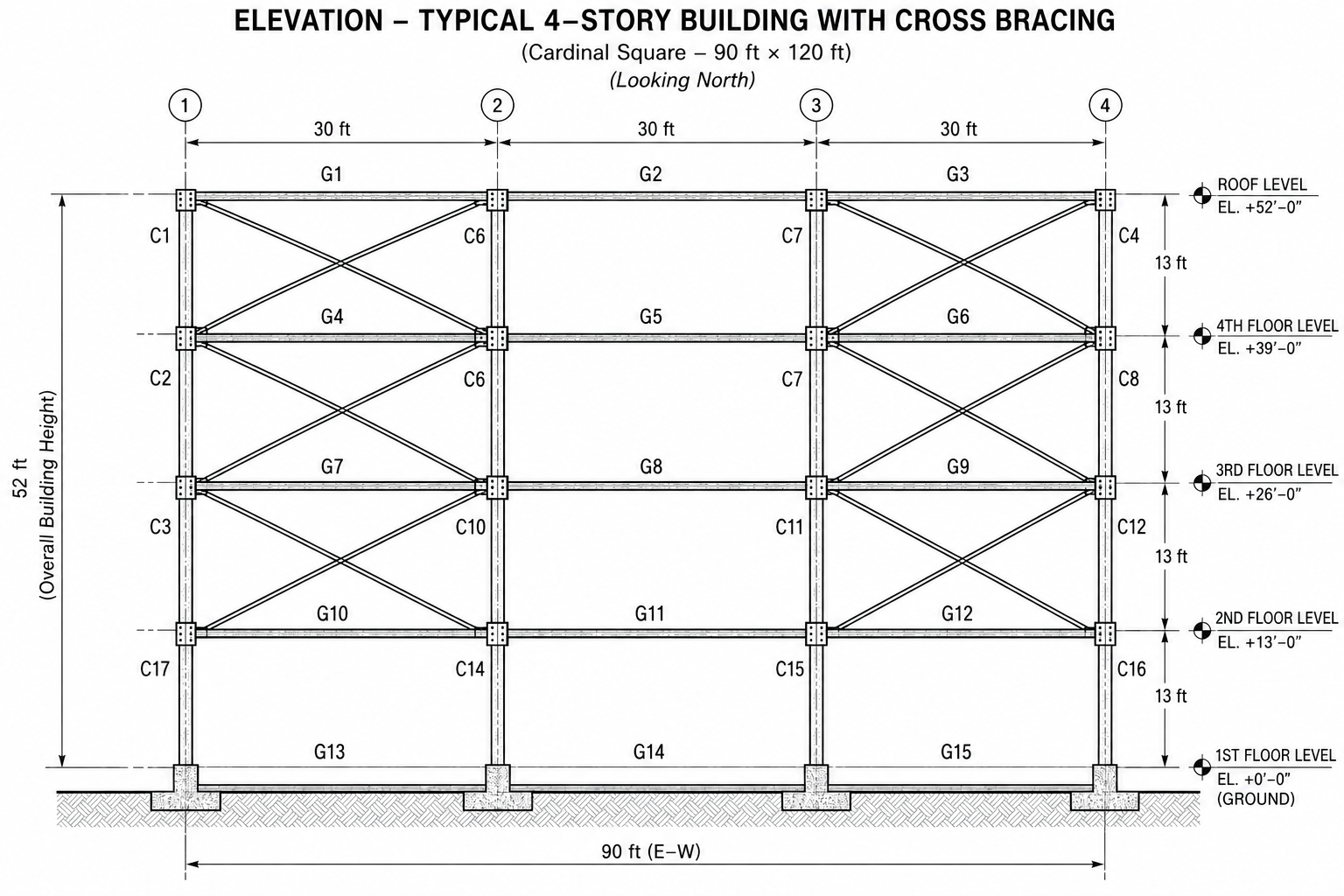
  • Elevation: 4 stories @ 13 ft (52 ft to roof).
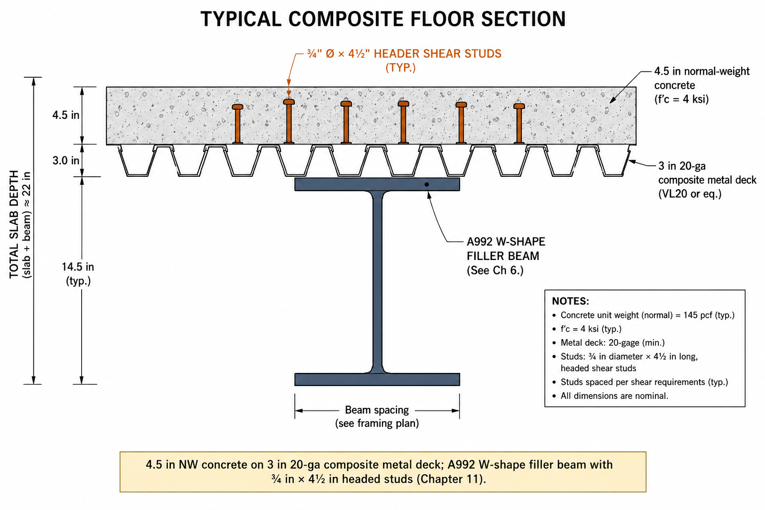
  • Floor: 4.5 in NW concrete on 3 in 20-ga composite metal deck.
  • Lateral system: Concentrically-braced frames (CBF) in the two perimeter bays each direction; interior gravity-only with simple shear tabs.
  • Members: A992 W-shapes; A572 Gr. 50 plates; A500 Gr. C HSS bracing; A325-N 7/8 in bolts; E70XX welds; F1554 Gr. 36 anchor rods.
  • Loads: Floor D = 75 psf, L = 50 psf. Roof D = 25 psf, Lr = 20 psf, S = 30 psf. Cladding 15 psf perimeter. Wind 110 mph, Exposure B. Seismic SDS = 0.30 g, R = 3.25 (OCBF).
1. Typical Floor Framing Plan
N30 ft30 ft30 ft30 ft30 ft30 ft30 ftB1B2B3B4B5B6B7B8B9B10B11B12B13B14B15B16B17B18B19B20B21B22B23B24G1G2G3G4G5G6G7G8G9G10G11G12G13G14G15C1C2C3C4C5C6C7C8C9C10C11C12C13C14C15C16C17C18C19C20Typical Floor Framing Plan — Cardinal Square (90 ft × 120 ft)3 bays E–W × 4 bays N–S @ 30 ft. Filler beams @ 10 ft o.c. (dashed). Columns C1–C20.
Filler beams B1–B24 @ 10 ft o.c. (dashed) spanning N–S between girders G1–G16 on E–W column lines. Columns C1–C20 at every grid intersection. Plan 90 ft × 120 ft.
2. Building Elevation
Building Elevation (E–W) — 4 stories × 13 ft, 3 bays × 30 ft13 ft13 ft13 ft13 ftRoofL4L3L2L130 ft30 ft30 ftHSS X-bracing in end bays (perimeter CBF) · gravity-only interior bays
Four 13 ft stories, three 30 ft bays. HSS X-braces in end bays for the lateral (CBF) system; interior bays are gravity-only with simple shear tabs.
3. Typical Composite Floor Section
Typical Composite Floor Section4.5 in normal-weight concrete (f′c = 4 ksi)3 in 20-ga composite metal deck (VLI20 or eq.)A992 W-shape filler beam (see Ch 6)¾″ Ø × 4½″ headed shear studsTotal depth (slab + beam) ≈ 22 in
4.5 in NW concrete on 3 in 20-ga composite metal deck; A992 W-shape filler beam with ¾ in × 4½ in headed studs (Chapter 11).
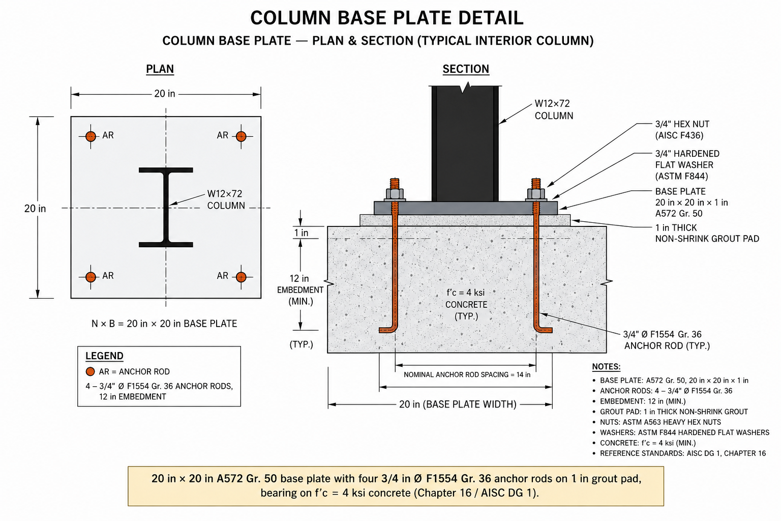
4. Column Base Plate Detail
Column Base Plate — Plan & Section (typical interior column)PlanN × B = 20 in × 20 in plateW12×72 columnARARARAR4 – ¾″ Ø F1554 Gr. 36 anchor rods, 12 in embedmentSection1″ grout padtp base plateW-columnBearing on f′c = 4 ksi concrete; tp from m, n, λn′ (AISC DG 1)
20 in × 20 in A572 Gr. 50 base plate with four ¾ in Ø F1554 Gr. 36 anchor rods on 1 in grout pad, bearing on f′c = 4 ksi concrete (Chapter 16 / AISC DG 1).

Weekly Roadmap · Fall 2026

Each row names the AISC chapter you are operating in, the design task, the Sunday submission, and the metrics your instructor will grade. Weights sum to 100% of the capstone portion of your course grade.

Week 1 · Ch 1 — Framing & member types
Aug 24 – Aug 28
5% of capstone

Focus: Group formation, kickoff, structural layout of Cardinal Square.

Group tasks
  • Form groups of 3–4; assign PE, checker, drafter, spec lead.
  • Produce a framing plan of a typical floor + roof with members labeled.
  • Trace gravity load path: deck → filler → girder → column → base plate → footing.
Evaluation metrics
  • Framing correctness
  • Member labeling
  • Load path clarity
  • Drawing quality
Submission — S1 — Framing plan PDF + 1-page load-path narrative. · Due Sunday 11:59 pm as CS-<Group>-W<#>.pdf
Week 2 · Ch 2 — Loads & LRFD combos
Aug 31 – Sep 4
5% of capstone

Focus: ASCE 7-22 load takeoff and governing LRFD combinations.

Group tasks
  • Tabulate D, L, Lr, S, W, E at roof and typical floor.
  • Apply live-load reduction (§4.7) to columns and girders.
  • Report wu on a typical filler beam and Pu on a typical interior column.
Evaluation metrics
  • Correct ASCE 7 magnitudes
  • Live-load reduction
  • Full combo enumeration
  • Unit checks
Submission — S2 — Load takeoff + governing combo table. · Due Sunday 11:59 pm as CS-<Group>-W<#>.pdf
Week 3 · Ch 3 — Materials & sections
Sep 7 – Sep 11
5% of capstone

Focus: Materials memo and section-property calcs for trial shapes.

Group tasks
  • Justify A992, A572 Gr.50, A500 Gr.C, A325-N, E70XX.
  • Compute Ix, Sx, Zx, shape factor for two trial W-shapes.
  • Prepare a one-page materials sheet.
Evaluation metrics
  • Correct Fy/Fu/E
  • Zx/Sx from first principles
  • Shape-factor discussion
Submission — S3 — Materials memo + section-property sheet. · Due Sunday 11:59 pm as CS-<Group>-W<#>.pdf
Week 4 · Ch 4 — Tension members
Sep 14 – Sep 18
10% of capstone

Focus: Design the CBF diagonal brace and its gusset.

Group tasks
  • Compute Tu from story shear and brace geometry.
  • Check gross yielding, effective-net rupture with U (Table D3.1).
  • Verify block shear at gusset; select HSS or 2L.
Evaluation metrics
  • Correct U
  • Both limit states
  • Block-shear geometry
  • Utilization stated
Submission — S4 — Tension calc package + gusset diagram. · Due Sunday 11:59 pm as CS-<Group>-W<#>.pdf
Week 5 · Ch 5 — Compression
Sep 21 – Sep 25
10% of capstone

Focus: Interior gravity column at Level 1.

Group tasks
  • Assemble Pu at base with LL reduction.
  • Pick trial W12/W14 (Table 4-1a); verify Fcr §E3.
  • Confirm φcPn ≥ Pu.
Evaluation metrics
  • Correct K
  • Buckling regime
  • Full φcPn
Submission — S5 — Column calc + Table 4-1a excerpt. · Due Sunday 11:59 pm as CS-<Group>-W<#>.pdf
Week 6 · Ch 6 — Flexure
Sep 28 – Oct 2
10% of capstone

Focus: 30 ft filler beam gravity flexure.

Group tasks
  • Compute Mu = wuL²/8.
  • Select from Table 3-2; verify Lb < Lp.
  • Report φbMn ≥ Mu.
Evaluation metrics
  • Correct Lp, Lr
  • Cb applied
  • Mp from first principles
Submission — S6 — Beam flexure calc + Mn vs Lb annotated. · Due Sunday 11:59 pm as CS-<Group>-W<#>.pdf
Week 7 · Ch 7 — Shear
Oct 5 – Oct 9
5% of capstone

Focus: Support shear on the Week 6 filler beam.

Group tasks
  • Compute Vu = wuL/2.
  • Compute φvVn per Ch G.
  • Confirm h/tw slenderness.
Evaluation metrics
  • Correct Aw
  • Cv1 regime
  • Utilization reported
Submission — S7 — Shear calc + slenderness check. · Due Sunday 11:59 pm as CS-<Group>-W<#>.pdf
Week 8 · Ch 8 — Combined forces
Oct 12 – Oct 16 · MIDTERM
15% of capstone

Focus: Beam-column check + full Ch 1–8 rollup.

Group tasks
  • Assemble Pu + Muy from wind + gravity.
  • Apply H1-1a / H1-1b.
  • Compile midterm binder + slides.
Evaluation metrics
  • Correct H1 branch
  • Cross-referenced calcs
  • Presentation
  • Consistency
Submission — S8 — Midterm calc binder + 10 slides (oral review Mon Oct 19). · Due Sunday 11:59 pm as CS-<Group>-W<#>.pdf
Week 9 · Ch 9 — Second-order effects
Oct 19 – Oct 23
5% of capstone

Focus: B1 / B2 amplification, re-check interaction.

Group tasks
  • Compute B1 with Cm, Pe1.
  • Compute B2 story-drift approach.
  • Re-run H1 with amplified moments.
Evaluation metrics
  • Correct Cm, α
  • Pe1 and Pe,story
  • Governing moment
Submission — S9 — Amplified moment calc + revised H1. · Due Sunday 11:59 pm as CS-<Group>-W<#>.pdf
Week 10 · Ch 11 — Composite construction
Oct 26 – Oct 30
5% of capstone

Focus: Make the filler beam composite with 4.5 in slab.

Group tasks
  • Determine ΣQn and select 3/4 in studs.
  • Read Table 3-19 or compute φbMn.
  • Report stud layout.
Evaluation metrics
  • Effective flange width
  • Full vs partial composite
  • Stud count per §I8
Submission — S10 — Composite beam calc + stud-layout sketch. · Due Sunday 11:59 pm as CS-<Group>-W<#>.pdf
Week 11 · Ch 12 — Bolted connections
Nov 2 – Nov 6
5% of capstone

Focus: Filler-to-girder shear tab, 3 A325-N 7/8 in bolts.

Group tasks
  • Check bolt shear φRn = 0.75·Fnv·Ab.
  • Check bearing/tearout §J3.7/§J3.11.
  • Verify edge distance/spacing.
Evaluation metrics
  • Threads-in vs excluded
  • Bearing vs tearout governs
  • Detail per AISC minimums
Submission — S11 — Shear-tab calc + detail. · Due Sunday 11:59 pm as CS-<Group>-W<#>.pdf
Week 12 · Ch 13 — Welded connections
Nov 9 – Nov 13
5% of capstone

Focus: Fillet weld of brace gusset to column flange.

Group tasks
  • Size w from φRn.
  • Verify min weld size (Table J2.4).
  • Detail gusset with weld symbols.
Evaluation metrics
  • Correct effective throat
  • Min-size compliance
  • Symbol accuracy
Submission — S12 — Weld calc + AWS symbol detail. · Due Sunday 11:59 pm as CS-<Group>-W<#>.pdf
Week 13 · Ch 16 + Ch 18
Nov 16 – Nov 20
10% of capstone

Focus: Base plate + deflection.

Group tasks
  • Size N × B for concrete bearing §J8.
  • Compute tp from m, n, λn′.
  • Confirm ΔL ≤ L/360.
Evaluation metrics
  • Bearing pressure check
  • Plate thickness governs
  • Composite Ix source
Submission — S13 — Base plate + deflection calc. · Due Sunday 11:59 pm as CS-<Group>-W<#>.pdf
Week 14 · Integration
Nov 23 – Nov 27 (async)
5% of capstone

Focus: Assemble final calc binder and drawing set.

Group tasks
  • Compile all S1–S13.
  • Structural drawings S-100 to S-500.
  • Peer review swap.
Evaluation metrics
  • Consistency
  • AISC section per check
  • Drawing readability
Submission — S14 — Draft final report + drawings. · Due Sunday 11:59 pm as CS-<Group>-W<#>.pdf
Week 15 · Final report & presentation
Nov 30 – Dec 4
5% of capstone

Focus: Polish and rehearse.

Group tasks
  • Integrate peer comments.
  • 12–15 slide final deck.
  • Rehearse Q&A.
Evaluation metrics
  • Narrative coherence
  • Traceability
  • Slide clarity
Submission — S15 — Final report + deck + dry-run. · Due Sunday 11:59 pm as CS-<Group>-W<#>.pdf
Finals · Final oral defense
Dec 7 – Dec 11
10% of capstone

Focus: 30-min group presentation + individual Q&A.

Group tasks
  • Present design philosophy → base plate.
  • Each member owns one chapter.
  • Submit signed binder + drawings.
Evaluation metrics
  • Individual mastery
  • Group cohesion
  • Deliverable completeness
Submission — S16 — Final defense + signed binder. · Due Sunday 11:59 pm as CS-<Group>-W<#>.pdf

Overall Grading Rubric

ComponentWeight
Weekly submissions S1–S1660%
Midterm gate (S7, Week 8)15%
Final report quality10%
Final oral defense10%
Peer & instructor evaluation5%
Total100%

Weekly Expectations & Submission Standards

  • Cover sheet: project name, group #, week #, member names & signatures.
  • All calcs typeset (hand-written scans only if legible + indexed).
  • AISC 360-22 section cited for every check (§F2.2, §E3, §H1-1a, §J3.7, …).
  • Governing limit state boxed and utilization ratio reported.
  • Assumptions consistent with prior weeks (loads, materials, geometry).
  • Peer-check sign-off line: reviewed by ____ on ____.
  • Late: −5% per calendar day, no credit after 7 days.
  • Every design decision must be defensible orally at the final review.