Welded Connections
Fillet, groove, weld symbols, and effective throat.
- AISC 360-22 §J2 — Welds
Lecture Notes
This module introduces welded connections. Lecture content here covers the governing physics, LRFD philosophy, and how the relevant AISC 360-22 chapter organizes the limit states.
Instructors can replace this text in Admin Mode. Each section is structured around: (1) behavior, (2) failure modes, (3) AISC limit-state equations, (4) design workflow, (5) detailing requirements.
A short comparison to ASD is included only where the resistance factor / safety factor relationship clarifies the LRFD design check.
Every chapter's worked example is one step in the design of the same building: Plan: 4 bays N–S × 3 bays E–W, each 30 ft × 30 ft. Stories: 4 @ 13 ft (52 ft roof). Composite floor: 4.5 in NW concrete on 3 VLI20 deck. Roof: 1.5 in B-deck + insulation + membrane. Materials: Wide-flange members A992 (Fy = 50 ksi, Fu = 65 ksi). Plates A572 Gr. 50. HSS bracing A500 Gr. C. Bolts A325-N 7/8 in dia. Welds E70XX. Concrete f'c = 4 ksi. Anchor rods F1554 Gr. 36.
Formula Sheet
| Name | Equation | AISC Ref |
|---|---|---|
| Fillet weld strength | φRn = 0.75 · 0.60 · FEXX · te · Lw | AISC §J2.4 |
| Effective throat | te = 0.707 · w (for equal-leg fillet) | AISC §J2.2 |
Worked Example
Welded Connections
- Limit state 1
- Limit state 2
- 1. Required strengthCompute Ru.
- 2. Trial sectionPick a trial from AISC shape tables Instructor should verify with official AISC Manual.
- 3. Check each limit stateApply φ Rn ≥ Ru for every governing limit state.
- 4. IterateResize until the most economical section satisfies all checks.
- Skipping a limit state
- Using the wrong φ factor
- Forgetting serviceability checks
FE-Style Worked Examples (7)
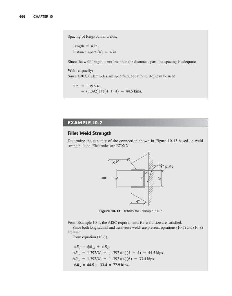
Each example mirrors the NCEES FE Civil Reference Handbook style: brief givens, a labeled figure, AISC section reference, step-by-step numeric solution, and a single boxed answer.
- te0.707 × 0.25 = 0.177 in
- φRn / in0.75 × 0.60 × 70 × 0.177 = 5.57 k/in
- Rule of thumb≈ 1.392·D (D in 1/16") = 1.392×4 = 5.57 k/in ✓
Textbook — Aghayere & Vigil (2009)(4 worked examples with figures + numerical answers)
Worked examples scanned directly from the CEGR 436 course textbook. Each card shows the original page (figure + full step-by-step solution) and adds an FE-style numerical multiple-choice prompt with answer key.
Chapter 10 covers fillet, groove, and plug welds. Fillet welds are governed by shear on the effective throat (te = 0.707·w for equal-leg). The base metal must also be checked — weld design rarely controls when E70 electrodes are matched with A36/A992 base.
- Fillet weld: φRn = 0.75·0.60·FEXX·te·Lw, FEXX = 70 ksi (E70).
- te = 0.707·w (equal-leg); for full-penetration groove, te = thickness of thinner part.
- Min fillet leg per Table J2.4 (driven by thicker part — 1/8 in to 5/16 in).
- Max fillet for ≥ 1/4 in plates: t − 1/16 in.
- Strength per inch of E70 fillet: 1.392·w (kips/in, w in 1/16) — handy formula.
- Eccentrically loaded weld groups: use Manual Tables 8-4 to 8-11 (or elastic vector method).
Interactive Calculator
Fillet Weld Strength
AISC §J2.4Longitudinal loading only. Use Instantaneous Center / directional strength increase for angled loads.
Practice Problems
- [E] State φ for fillet welds (0.75).
- [E] Compute te for a 5/16 in. equal-leg fillet (te = 0.707·w).
- [E] State FEXX for E70 (70 ksi).
- [E] State min and max fillet size rules (Table J2.4).
- [E] Sketch AWS symbol for a 1/4 in. fillet, both sides, 6 in. long.
- [M] 5/16 in. fillet, 8 in. long. Compute φRn (E70).
- [M] Lap splice 1/2 in. A36 plate with fillet top + bottom, total 12 in. Compute φRn.
- [M] L4x4x3/8 welded to gusset. Find Lw to develop Pu = 120 k.
- [M] Base-metal shear rupture check for 5/16 fillet on 1/2 A36 plate.
- [M] Eccentric weld group: use Table 8-4 IC method, 6 x 4 in. L-pattern, ex = 3 in.
- [H] Design CJP groove weld for flange splice in W21x62, Mu = 320 k-ft. Specify electrode, prep, NDT.
- [H] Fillet weld around HSS truss joint: design weld for Pu = 95 k tension diagonal.
- [H] Two-line fillet at a moment-tab connection; size for combined moment + shear.
- [H] 5/16 fillet 1/16 in. undersized over 20% length: compute % capacity reduction.
- [H] Base-plate weld: design 5/16 fillet on a 16 x 16 in. plate with Pu = 400 k, Mu = 75 k-ft.
- te = 0.707·w for equal-leg fillet weld.
- Min size from Table J2.4 depends on thicker connected part.
- Check base-metal shear rupture in addition to weld metal.
- AISC 360-22 §J2
- AISC Manual Tables 8-1 to 8-12
Quiz
Common Student Mistakes
- Mixing ASD and LRFD load combinations in the same problem.
- Using nominal strength Rn instead of design strength φRn.
- Forgetting to check every limit state listed in the AISC chapter.
"Professor Explains" Script
Today we're talking about welded connections. Think of this topic as one step in the LRFD workflow: identify the demand, identify the limit states from the relevant AISC chapter, then check that φ·Rn is at least equal to Ru. We'll walk through the failure modes, the equations, and a worked example. Pay close attention to where the resistance factor changes — that's where students lose points on exams.